











Что представляет собой флотационная машина SF с самовсасыванием?
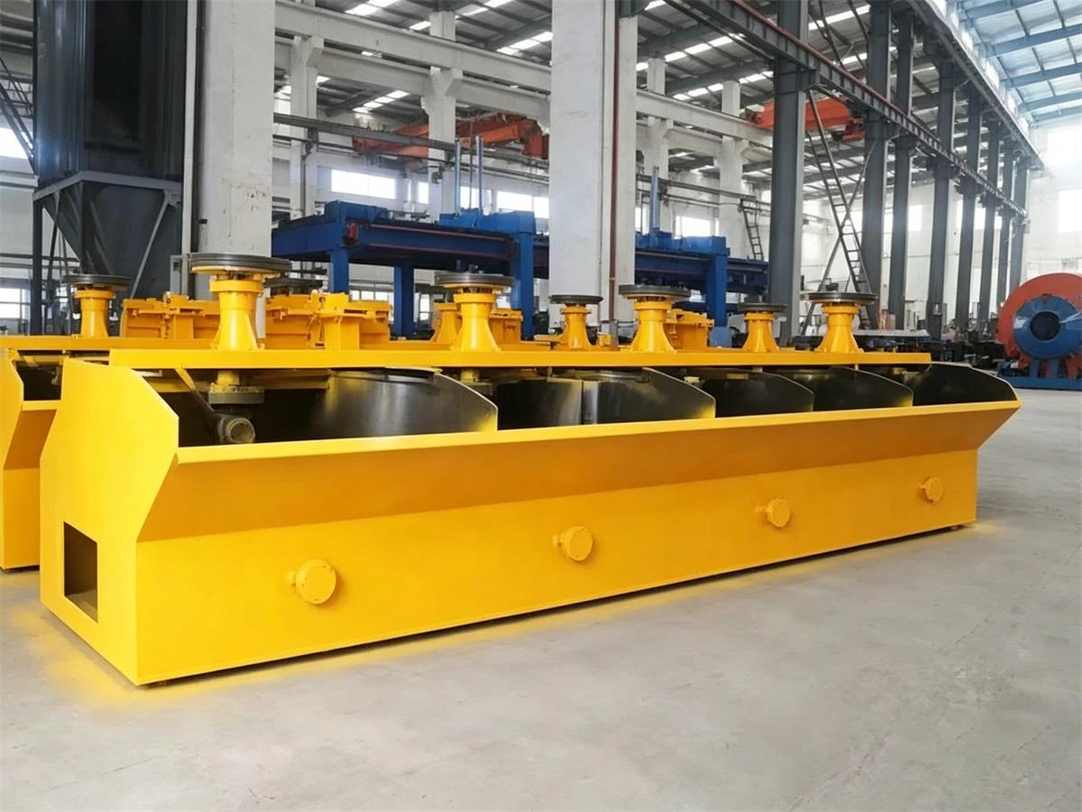
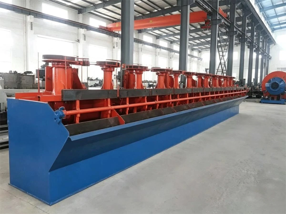
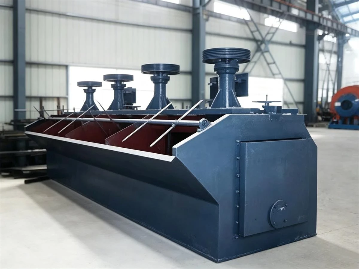
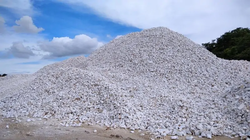
Флотационная машина SF с самовсасыванием, также известная как флотационная машина SF или флотационная машина с самовсасыванием пульпы, представляет собой механическое флотационное оборудование с перемешиванием, используемое для разделения ценных минералов из пульпы методом пенной флотации. Она главным образом применяется на обогатительных фабриках для обогащения медных, свинцово-цинковых, золотых, молибденовых, железных руд, графита, флюорита и других металлических и неметаллических минералов.
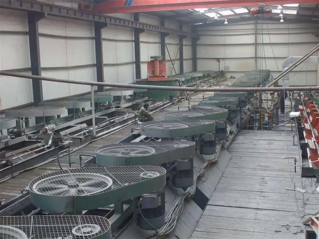
Флотационная машина SF объединяет в одном агрегате функции всасывания воздуха, всасывания пульпы и флотации. Вращающийся импеллер создаёт отрицательное давление, автоматически затягивая воздух и пульпу в камеру, обеспечивая достаточное перемешивание и диспергирование пузырьков для разделения минералов. В составе полной обогатительной фабрики флотационные машины SF обычно устанавливаются после операций измельчения, классификации и кондиционирования и широко применяются в контурах основной, контрольной и перечистной флотации. В зависимости от производительности фабрики и требований технологического процесса модели SF выпускаются с различным объёмом камеры; промышленные агрегаты обычно комплектуются камерами объёмом от нескольких кубических метров до более чем 10 м³ на камеру. Чтобы узнать больше, нажмите “Что такое флотационная машина?”
Как работает флотационная машина с самовсасыванием?
Флотационная машина SF с самовсасыванием работает за счёт совместного действия перемешивания импеллером, всасывания воздуха и флотации минералов. В процессе работы вращающийся импеллер создаёт отрицательное давление внутри камеры импеллера, автоматически затягивая воздух через полый вал и одновременно обеспечивая циркуляцию пульпы из камеры. Такая конструкция с самовсасыванием обеспечивает непрерывное перемешивание пульпы и диспергирование воздуха без необходимости во внешней системе подачи воздуха.
Перемешивание пульпы и всасывание воздуха
Электродвигатель приводит во вращение импеллер, создавая перепад давления в камере импеллера. Верхние лопасти затягивают воздух во флотационную машину, а нижние лопасти обеспечивают циркуляцию пульпы со дна камеры для поддержания частиц во взвешенном состоянии и уменьшения осаждения крупных частиц.
Прикрепление минералов к пузырькам
Импеллер диспергирует поступающий воздух на мелкие пузырьки и равномерно смешивает их с пульпой. Под действием флотационных реагентов частицы ценных минералов прикрепляются к поверхности пузырьков, образуя минерализованные пузырьки для разделения.
Сбор и извлечение пены
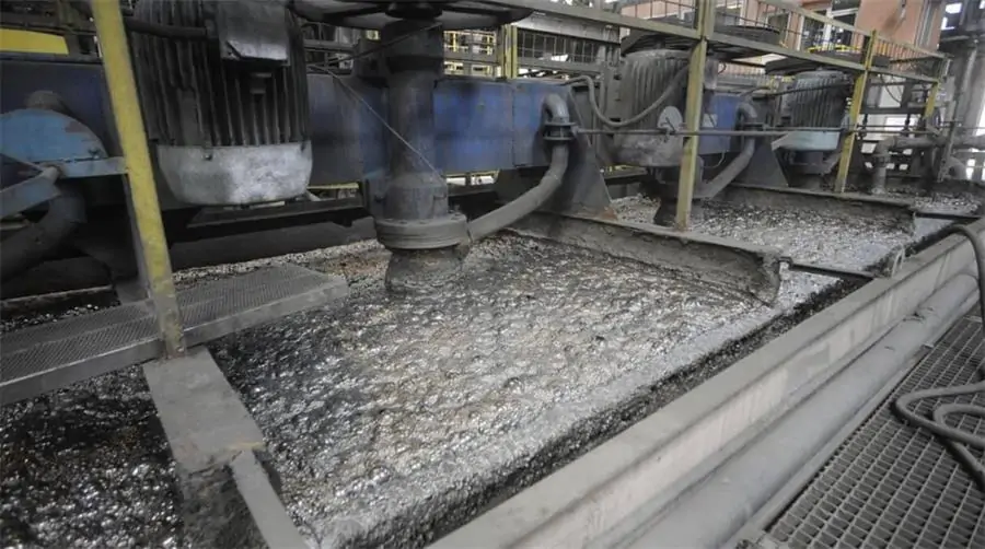
Минерализованные пузырьки поднимаются на поверхность и образуют слой пены, который снимается скребковым механизмом в виде концентрата. Оставшаяся пульпа продолжает движение по флотационному контуру для дальнейшего разделения; несколько машин SF обычно устанавливаются последовательно для операций основной, контрольной и перечистной флотации.
Конструкция флотационной машины SF с самовсасыванием
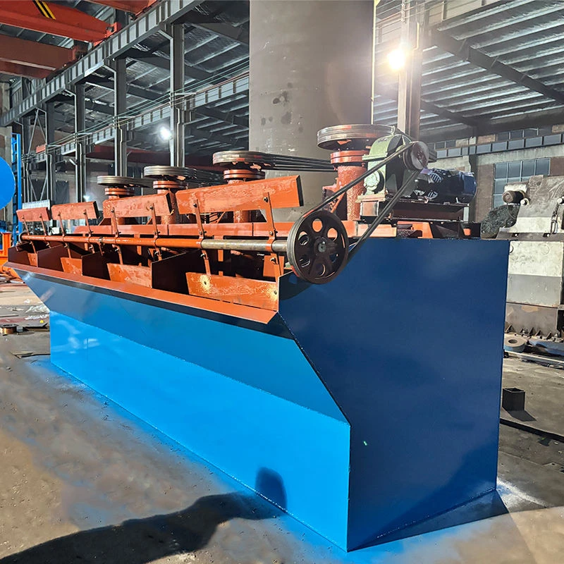
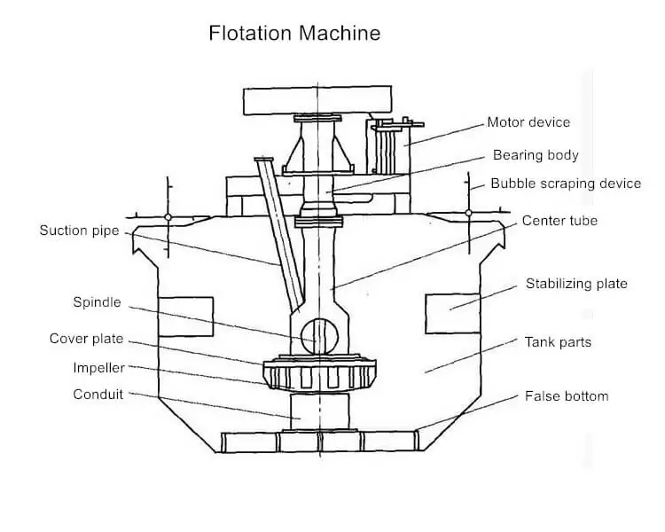
Флотационная машина SF с самовсасыванием состоит из системы импеллер-статор, системы циркуляции воздуха и пульпы, флотационной камеры и приводного узла, образуя законченную флотационную конструкцию.
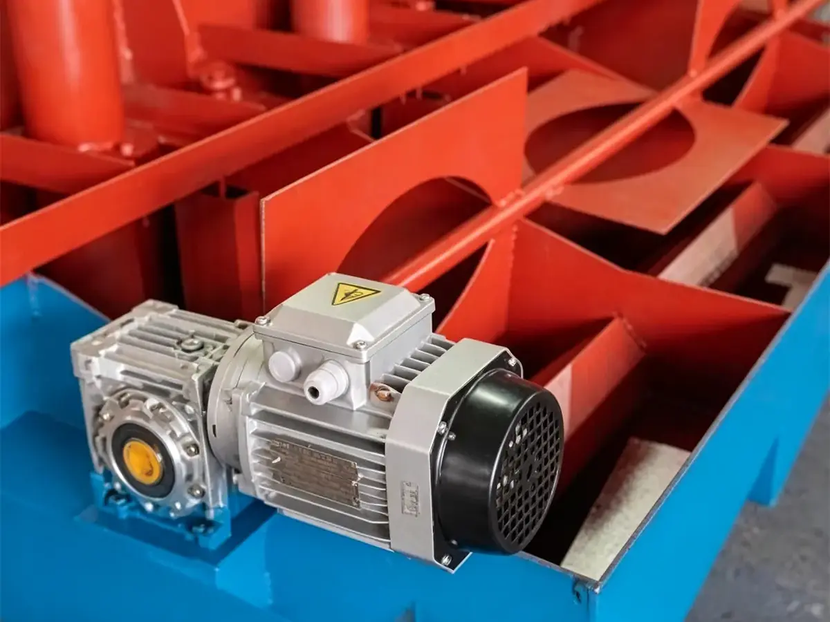
Червячный редукторный электродвигатель
Он приводит вал пеносъёмника на поверхности флотационной камеры, вызывая вращение скребковых лопастей и съём концентратной пены с поверхности жидкости. Является составной частью системы съёма пены.
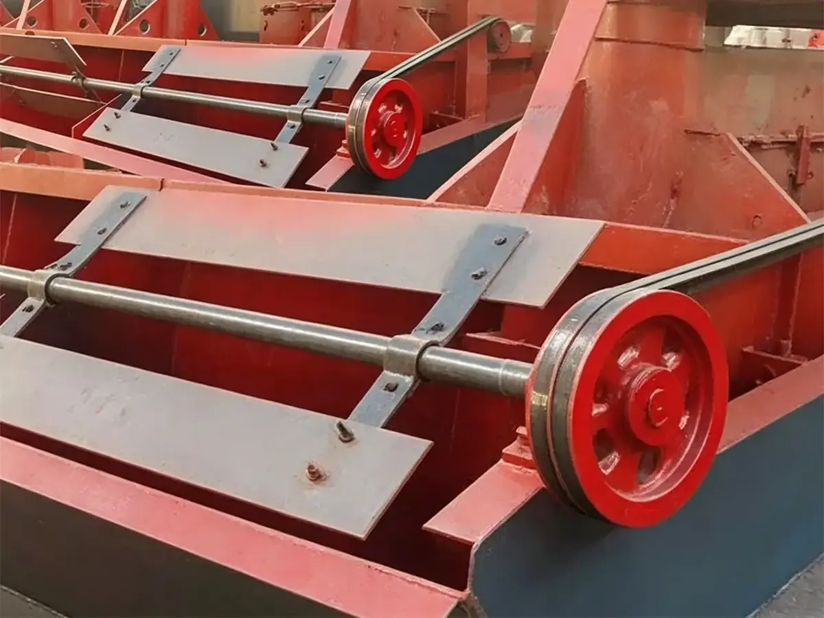
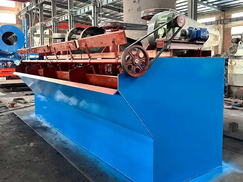
Вал скребка, скребковые лопасти и шкив в сборе
Этот узел представляет собой механизм съёма пены флотационной машины; красный элемент — это шкив, длинный вал служит главным шпинделем пеносъёмника, а стальная пластина выполняет роль скребковой лопасти. Электродвигатель приводит этот вал через ремень для непрерывного съёма пены.
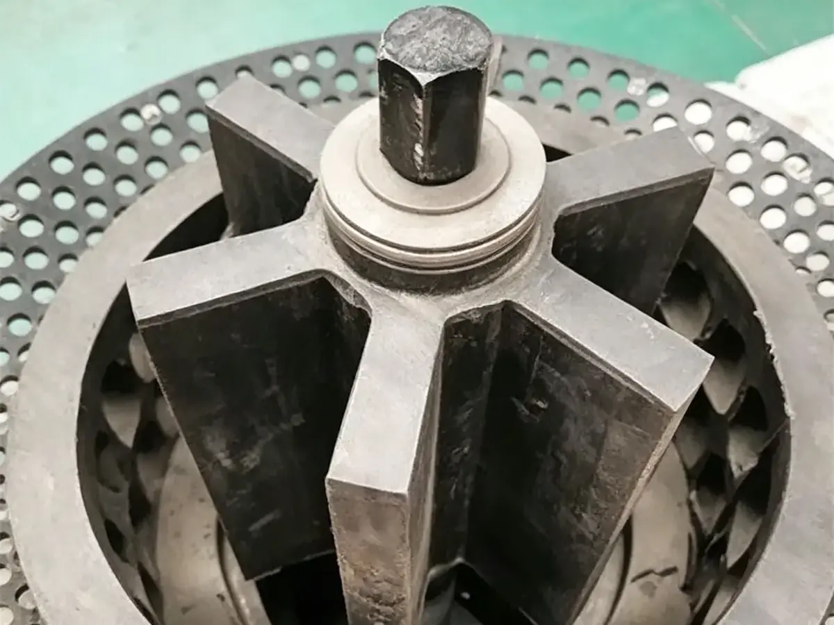
Импеллер и статор в сборе
Ключевые быстроизнашивающиеся детали (компоненты перемешивания и аэрации): вращающийся импеллер создаёт отрицательное давление для затягивания воздуха и перемешивания пульпы, а перфорированный наружный диск служит статором (крышкой), стабилизируя поток пульпы и сдвигая пузырьки воздуха — это “сердце” флотационной машины.
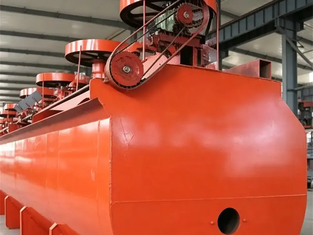
Флотационная камера
Основной корпус машины состоит из кожуха, удерживающего пульпу и служащего реакционной зоной флотации; главный вал с механизмом перемешивания и устройство съёма пены устанавливаются над камерой. Флотационная машина SF имеет конструкцию камеры U-образной формы с наклоном вперёд.
Технические характеристики
Приведённая ниже таблица технических характеристик содержит подробную информацию по каждой модели флотационной машины SF, помогая заказчикам сравнивать различные конфигурации и выбирать подходящее оборудование в соответствии с требованиями к переработке.
| Модель | Эффективный объём (м³) | Диаметр импеллера (мм) | Частота вращения импеллера (об/мин) | Производительность (м³/мин) | Электродвигатель импеллера | Электродвигатель скребка | Габариты камеры (мм) | Масса (т) | Объём всасываемого воздуха (м³/м·мин) | ||
| Модель | Мощность (кВт) | Модель | Мощность (кВт) | ||||||||
| SF-0.37 | 0.37 | 296 | 386 | 0.2–0.4 | Y90L-4 | 1.5 | Y801-4 | 0.55 | 700×700×750 | 0.47 | 0.9–1.0 |
| SF-0.65 | 0.65 | 350 | 400 | 0.3–0.9 | Y132S-6 | 3 | Y90L-6 | 1.1 | 900×900×900 | 0.93 | 0.9–1.0 |
| SF-1.2 | 1.2 | 450 | 312 | 0.6–1.2 | Y132M2-6 | 5.5 | Y90L-6 | 1.1 | 1100×1100×1100 | 1.37 | 0.9–1.0 |
| SF-2.8 | 2.8 | 550 | 270 | 1.5–3.5 | Y160L-6 | 11 | Y90L-6 | 1.1 | — | 2.13 | 0.9–1.0 |
| SF-4 | 4 | 650 | 220 | 2–4 | Y200L-8 | 15 | Y100L-6 | 1.5 | 1850×2050×1200 | 2.58 | 0.9–1.0 |
| SF-8 | 8 | 760 | 191 | 4–8 | Y250M-8 | 30 | Y100L-6 | 1.5 | 2200×2900×1400 | 4.13 | 0.9–1.0 |
| SF-10 | 10 | 760 | 191 | 5–10 | Y250M-8 | 30 | Y100L-6 | 1.5 | 2200×2900×1700 | 4.49 | 0.9–1.0 |
| SF-16 | 16 | 850 | 169–193 | 5.0–16 | — | 45 | — | — | — | 7.415 | 0.9–1.0 |
| SF-20 | 20 | 730 | 186 | 5.0–20 | — | 30×2 | — | — | — | 9.823 | 0.9–1.0 |
Преимущества
SF Flotation Cell is designed for efficient mineral separation with integrated air suction, slurry circulation, and flotation functions. Its self-suction structure, optimized impeller system, and wear-resistant components provide stable flotation performance, lower energy consumption, and easier maintenance.
Области применения
SF Type Self Suction Flotation Cell is mainly applied in roughing and scavenging circuits of mineral processing plants. With its integrated air suction, slurry suction, and flotation functions, it is suitable for the separation of various metallic and non-metallic minerals, including sulfide ores, precious metals, and industrial minerals.If you’d like to learn more, click on “Типы флотационных машин для обогащения полезных ископаемых.”
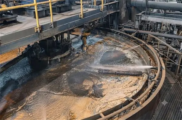

SF Flotation Cell in Flotation Plant Process
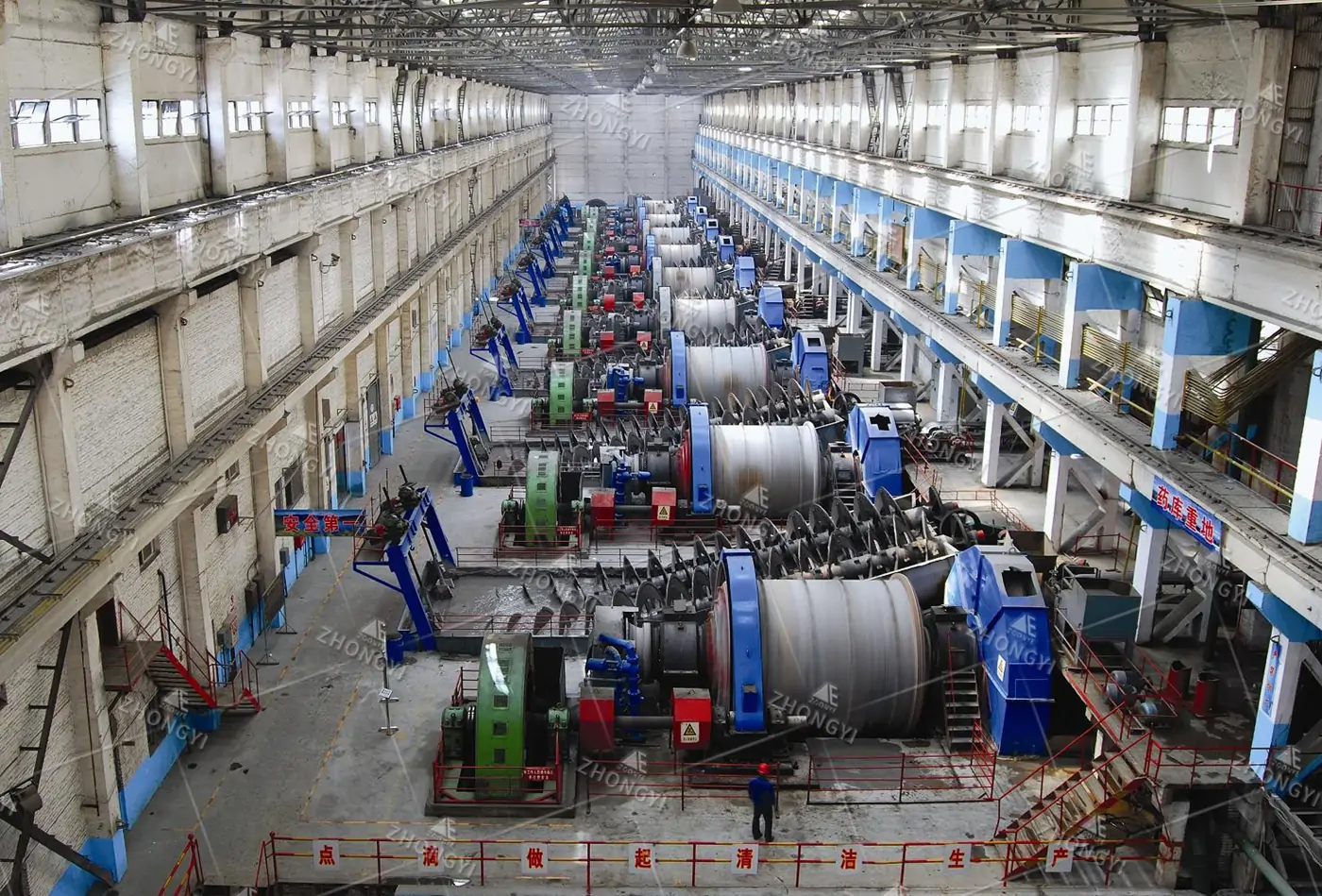
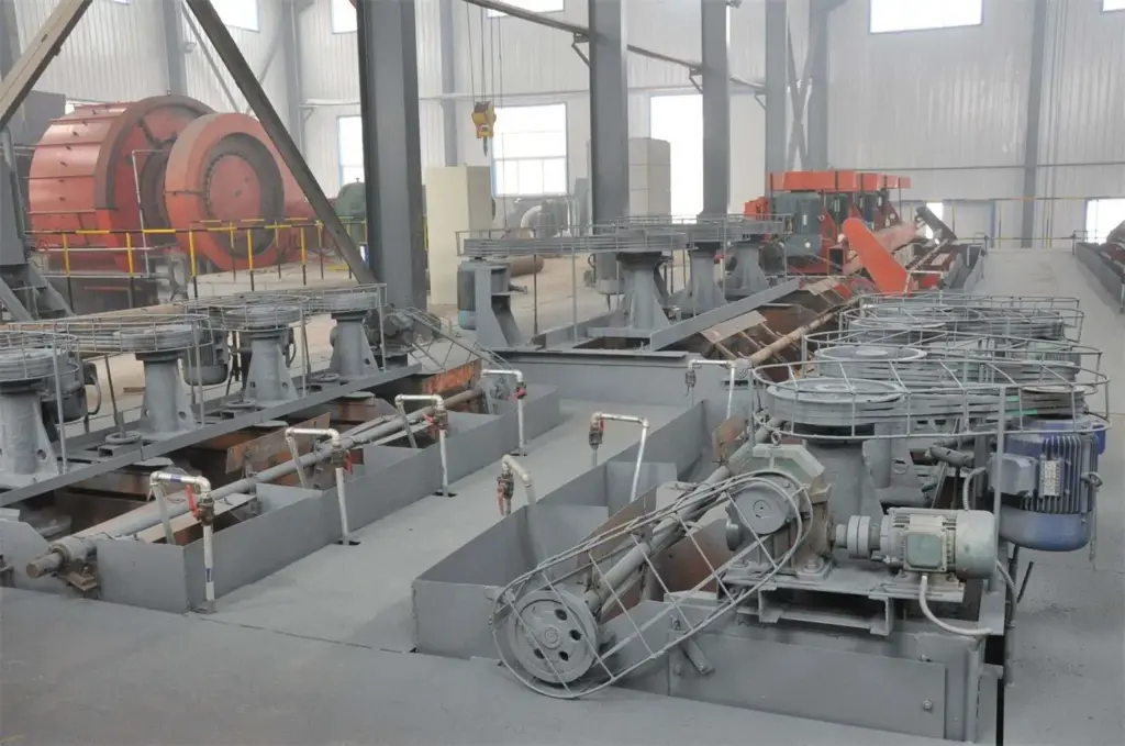
SF Type Flotation Cell is typically installed after grinding, classification, and conditioning processes as the main flotation equipment for mineral separation. It is widely applied in roughing, scavenging, and cleaning circuits, using its self-air suction and slurry suction design to provide continuous pulp aeration and mixing without external air supply systems.
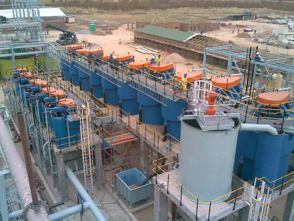
In a flotation plant, multiple SF Flotation Cells can be connected in series to complete continuous separation operations. The self-suction structure simplifies flotation circuit arrangement and allows flexible horizontal installation. SF cells can also be combined with JJF flotation cells to form flotation machine groups, which are commonly used for optimizing flotation layouts in medium and large beneficiation plants.
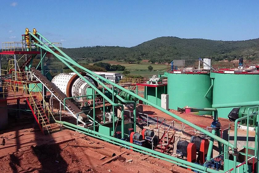
Projects Show
How to Choose the Right SF Type Flotation Cell?
Based on our project experience, SF Type Flotation Cell selection starts with the required processing capacity and flotation circuit design. The cell volume and quantity should match the plant throughput and flotation stages. For example, SF-2.8, SF-4, and SF-8 models are commonly used in small and medium beneficiation plants, while larger plants may require SF-10, SF-16, or combined flotation configurations. The final selection should be based on slurry flow, residence time, and the requirements of roughing, scavenging, and cleaning circuits.
Below are the selection recommendations summarized by our engineers:
Confirm Processing Capacity
Choose the flotation cell model according to the required ore processing capacity and plant scale.
Check Ore Characteristics
Select the cell based on ore type, particle size, mineral properties, and flotation difficulty.
Choose the Right Cell Volume
Match the flotation cell volume with slurry flow rate and required flotation residence time.
Consider Flotation Stage
Rougher, cleaner, and scavenger flotation require different flotation performance and configurations.
Evaluate Mixing and Aeration Performance
Choose equipment with stable agitation, uniform air dispersion, and efficient mineral-bubble contact.
Consider Energy Consumption
Select a flotation cell with efficient power usage to reduce long-term operating costs.
Check Wear Resistance and Maintenance
Prioritize durable impellers, stators, and easy-maintenance designs for continuous operation.
Select Based on Test Results
Use mineral processing tests to determine the suitable SF flotation cell model and configuration.
Choose an Experienced Manufacturer
Work with a professional flotation equipment supplier for proper selection and process optimization.
Why Choose Zhongyi?
Zhengzhou Zhongyi Mining Machinery Co., Ltd has been specializing in mining and mineral processing equipment manufacturing since 2010. Based in Zhengzhou, China, the company provides SF flotation cells, crushing equipment, screening equipment, and complete mineral processing solutions for different mining applications.
With 3 manufacturing bases covering more than 300 acres, Zhongyi Mining has established complete production capabilities, including CNC machining, laser cutting, welding, and equipment assembly. The company follows the ISO9001 quality management system and applies strict quality control throughout equipment design, manufacturing, and delivery.
In addition to supplying individual flotation machines, Zhongyi Mining provides technical support from equipment selection and process design to installation guidance and commissioning. With experience in mineral processing projects, we work with customers to develop practical flotation solutions based on ore characteristics, production capacity, and plant conditions.
Запросить индивидуальное решение
Partner with Zhongyi for SF Type Self Suction Flotation Cell solutions engineered for reliable mineral recovery, low energy consumption and stable operation in copper, gold, lead-zinc and other mineral beneficiation plants.
Customized XJK Flotation Machine Solutions
SF flotation cell selection and configuration depend on ore properties, processing capacity, and the existing plant layout. China Zhongyi Mining provides customized equipment recommendations based on actual project conditions, including flotation cell model selection, process arrangement, and equipment configuration. Our technical team can support projects from single flotation equipment supply to complete mineral processing plant solutions.
Please Provide the Following Information:
FAQs
What is an SF Type Self Suction Flotation Cell?
SF Type Self Suction Flotation Cell is a mechanical agitation flotation machine designed for mineral separation through the froth flotation process. It integrates air suction, slurry suction, and flotation functions in one unit. The impeller creates negative pressure to draw air and slurry into the chamber, providing continuous mixing and bubble dispersion for the recovery of valuable minerals.
What minerals can be processed by SF Flotation Cell?
SF Flotation Cells are suitable for processing a wide range of metallic and non-metallic minerals, including copper, gold, lead-zinc, molybdenum, iron ore, graphite, and fluorite. The actual application depends on mineral properties, feed conditions, and flotation requirements. Proper equipment selection helps match the flotation process with the characteristics of different ores.
What are the advantages of SF Flotation Cell compared with other flotation machines?
The main advantage of SF Flotation Cell is its self-suction design, which combines air intake, slurry circulation, and flotation functions in one machine. Compared with flotation systems requiring additional air supply equipment, SF cells offer flexible installation and simpler circuit arrangement. They are commonly used where reliable operation and practical process configuration are required.
How to choose the right SF Flotation Cell model?
The correct SF Flotation Cell model should be selected according to processing capacity, ore characteristics, slurry conditions, and flotation circuit design. Important factors include required cell volume, number of units, feed size, and flotation stages. Engineers usually evaluate the complete process flow rather than selecting equipment only based on production capacity.
Can SF Flotation Cells be used for roughing, scavenging, and cleaning stages?
Yes. SF Flotation Cells can be applied in roughing, scavenging, and cleaning circuits depending on the beneficiation process design. Multiple units are usually arranged in series to provide sufficient flotation time and continuous mineral separation. The final configuration depends on ore properties, target recovery requirements, and plant production capacity.
Does SF Flotation Cell require an external air blower?
No. SF Flotation Cell adopts a self-air suction structure, where the rotating impeller generates negative pressure to automatically draw air into the flotation chamber. This eliminates the need for external air supply equipment in suitable applications and helps simplify the flotation circuit layout while reducing auxiliary equipment requirements.
Can SF Flotation Cell be combined with JJF Flotation Cell?
Yes. SF Flotation Cell is often combined with JJF Flotation Cell to form a flotation machine group. In this configuration, SF cells typically work as suction cells, while JJF cells operate as direct-flow cells. This arrangement allows flexible flotation circuit design and is commonly used in medium and large beneficiation plants.
What information is needed to select a suitable SF Flotation Machine?
To recommend a suitable SF Type Flotation Cell, customers should provide basic project information, including ore type, processing capacity, feed size, slurry concentration, existing flotation process, and plant layout. Based on these conditions, engineers can evaluate the required flotation volume, equipment quantity, and suitable configuration for the specific application.