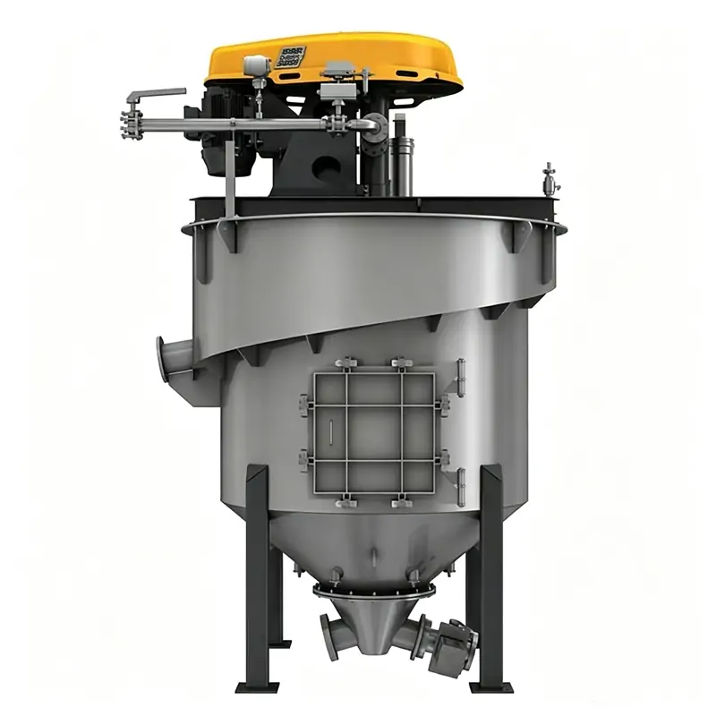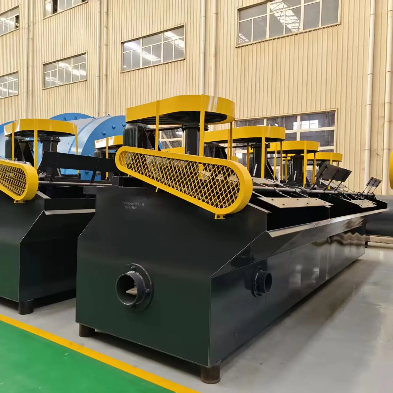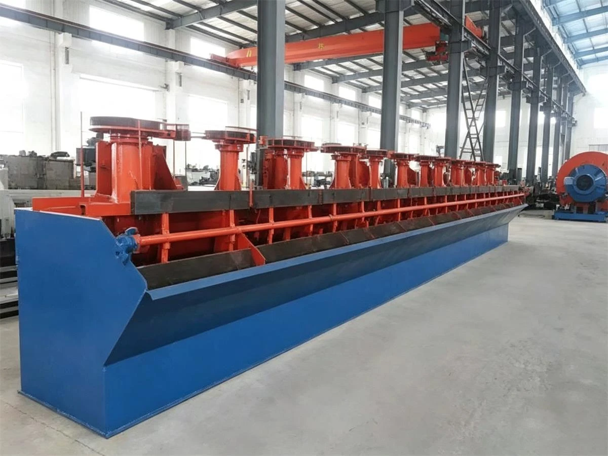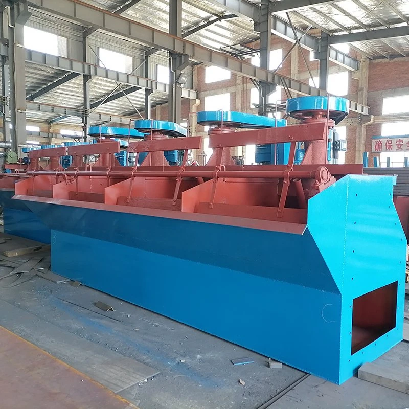












What Is a KYF Rougher Flotation Cell?
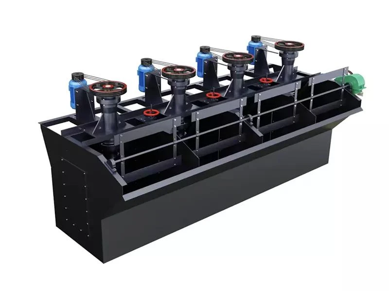
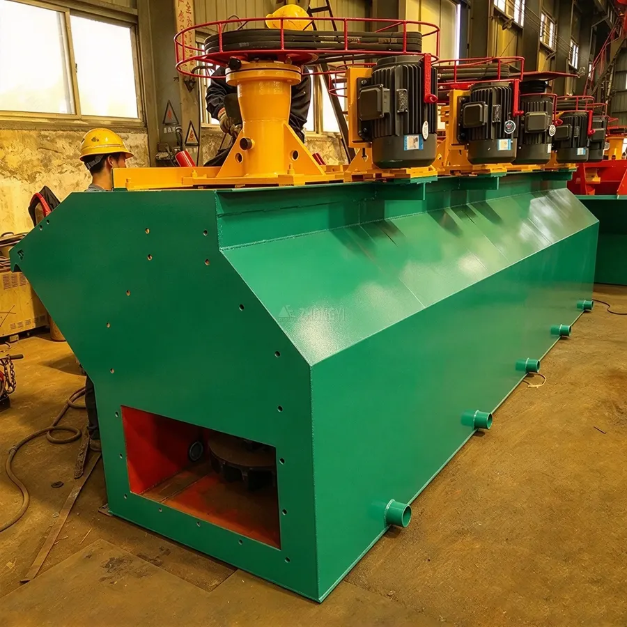
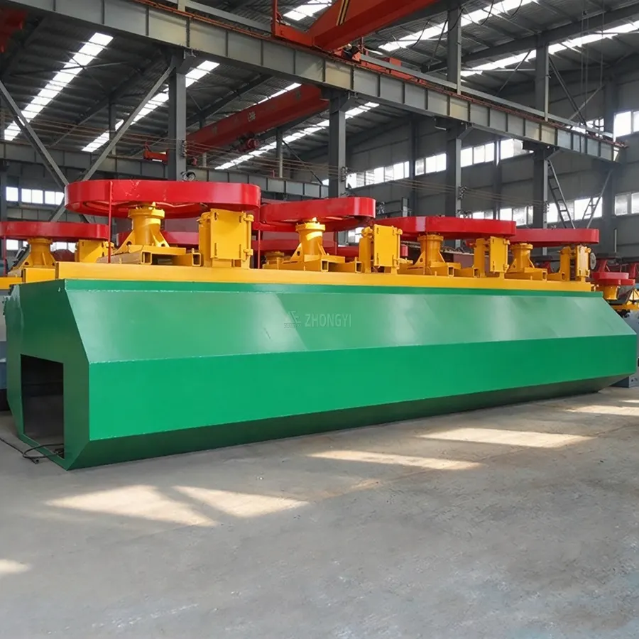
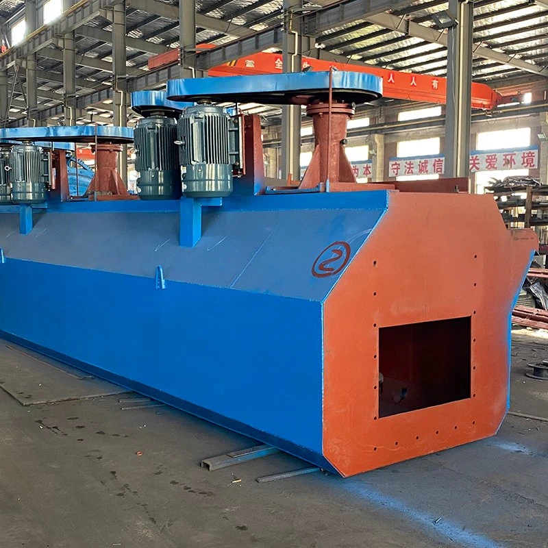
A KYF rougher flotation cells, also called a KYF air-inflation flotation machine, uses an external blower and mechanical impeller to disperse air into ore pulp and separate valuable minerals through froth flotation. It is commonly used in copper, lead-zinc, gold, and other ore beneficiation plants. Positioned after grinding and classification, it supports rougher flotation before subsequent scavenging or cleaning stages.
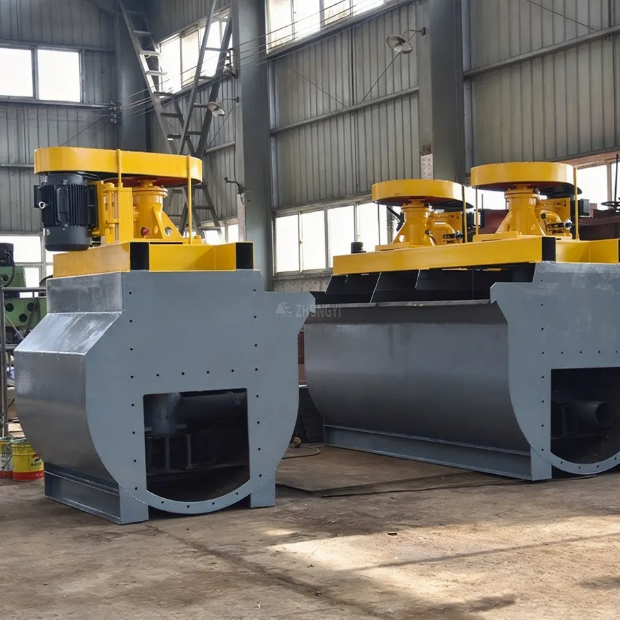
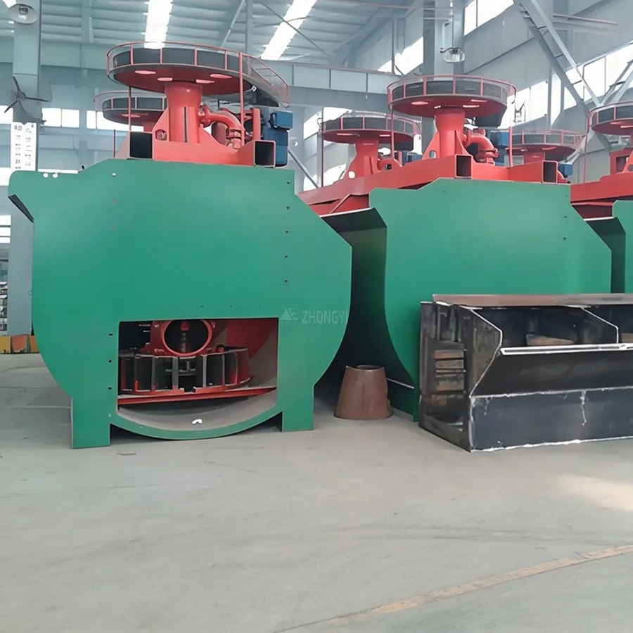
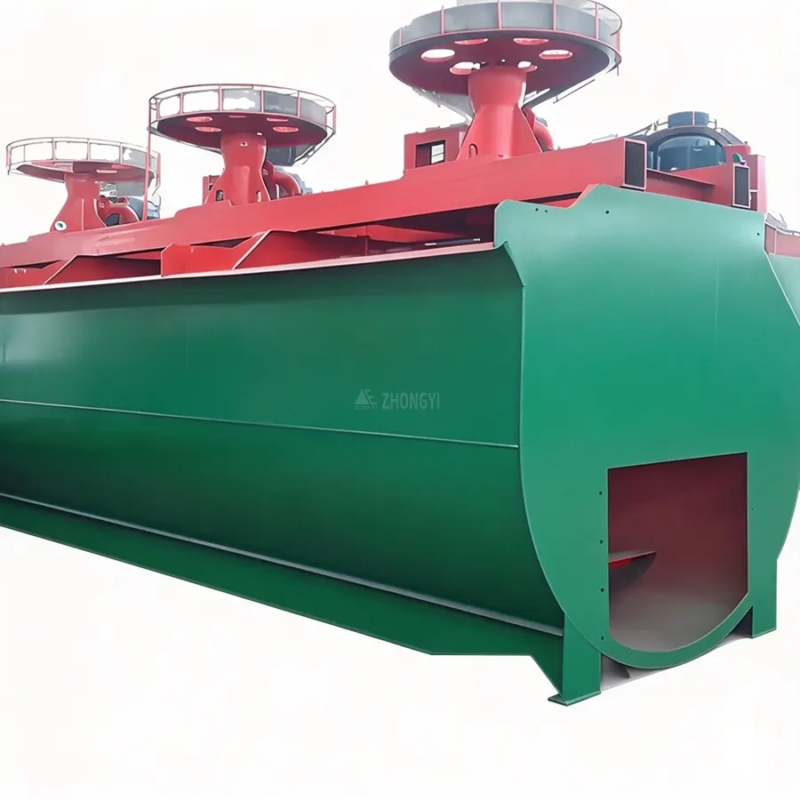
The KYF cell features a U-shaped tank, an impeller, a stator, and an air distributor to support pulp circulation and air dispersion. Unlike XCF flotation cells, KYF has no self-priming slurry function and requires a suitable pulp-transfer arrangement. Model selection should be based on ore properties, processing capacity, and flotation circuit requirements—not cell volume alone.
How Does a KYF Rougher Flotation Cell Work?
A KYF rougher flotation cell uses mechanical agitation and externally supplied air to separate valuable minerals from ore pulp. The impeller drives pulp circulation and promotes air dispersion, while the stator guides the flow through the tank.
KYF Flotation Cells Structure
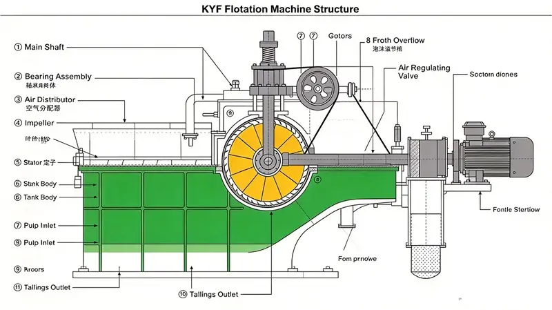
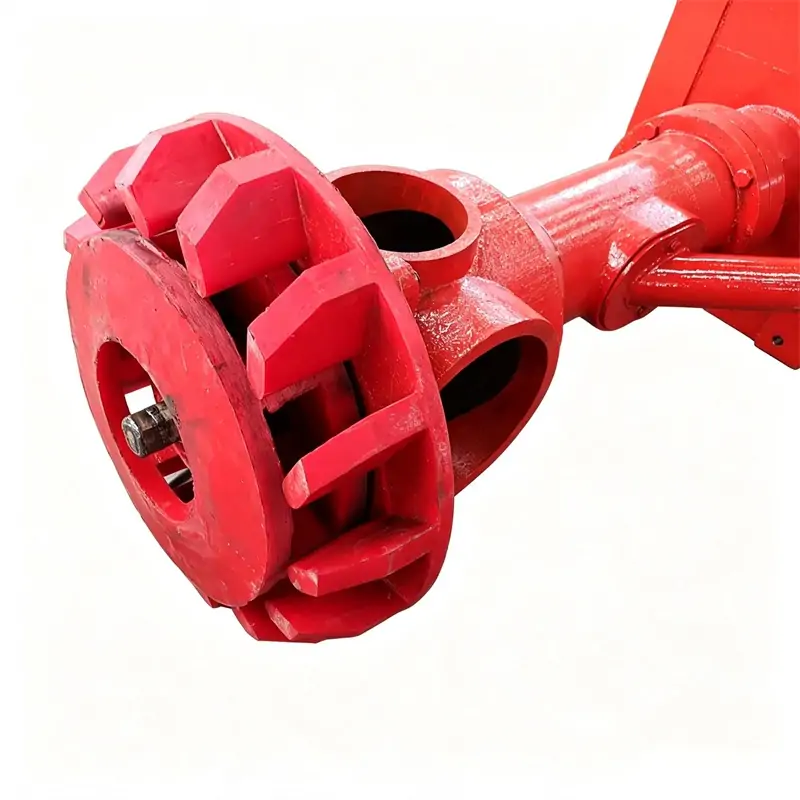
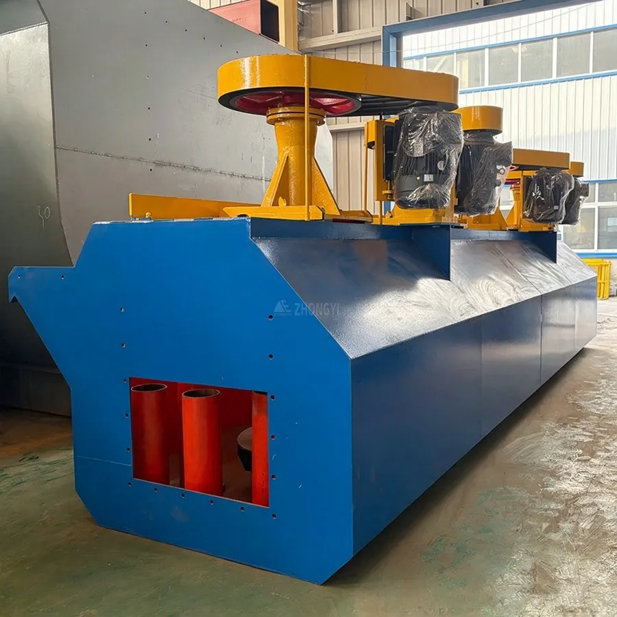
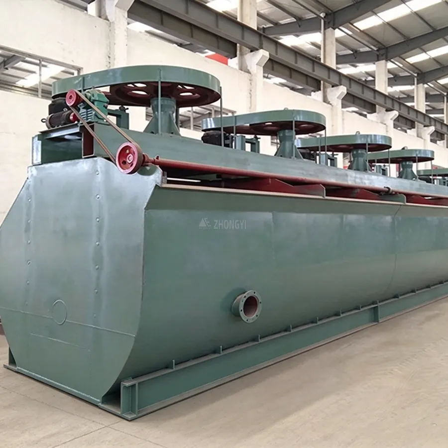
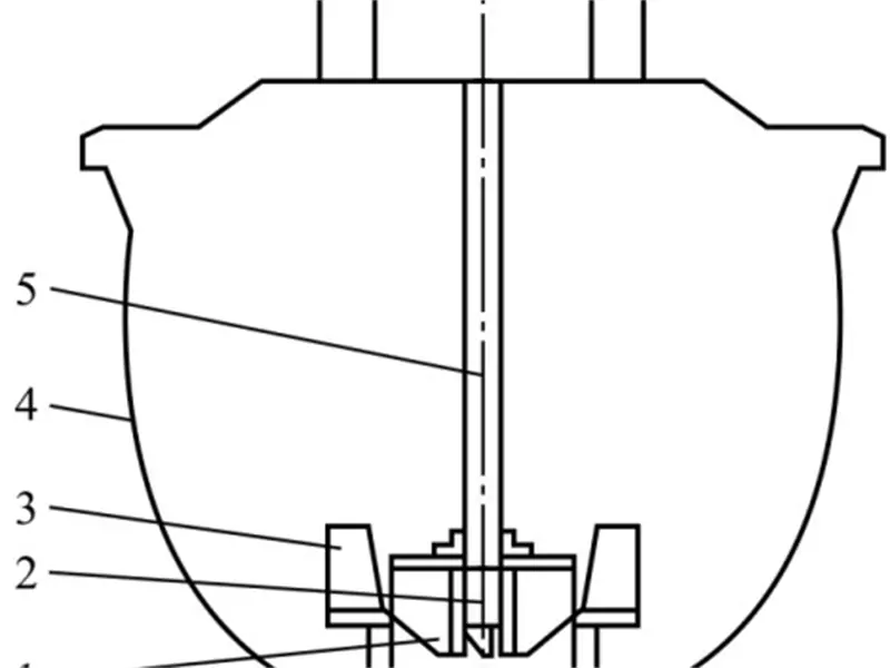
A KYF flotation cell consists of a flotation tank, impeller, stator, air distributor, hollow main shaft and air adjustment valve. These components work together to circulate pulp, disperse externally supplied air and maintain suitable mixing conditions for mineral flotation.
- U-Shaped Flotation Tank: Provides space for pulp circulation. The tank geometry helps limit settled solids when matched to the ore characteristics and operating conditions.
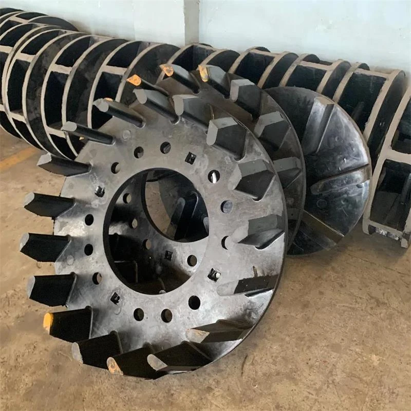
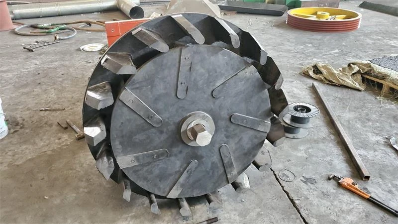
- Conical Impeller: Features backward-inclined blades that drive pulp circulation, suspend solid particles and promote air-pulp mixing.
- Air Distributor: A perforated cylindrical component inside the impeller assembly that distributes externally supplied air around the impeller, supporting bubble dispersion and mineral-bubble contact.
- Stator: Positioned around the impeller to guide the discharged pulp flow, reduce excessive rotational movement and support circulation within the tank.
- Hollow Main Shaft: Transmits rotational force to the impeller and provides an air passage to the air distributor.
- Air Adjustment Valve: Regulates the air supply according to operating requirements and flotation conditions.
Engineering Advantages of KYF Flotation Cells
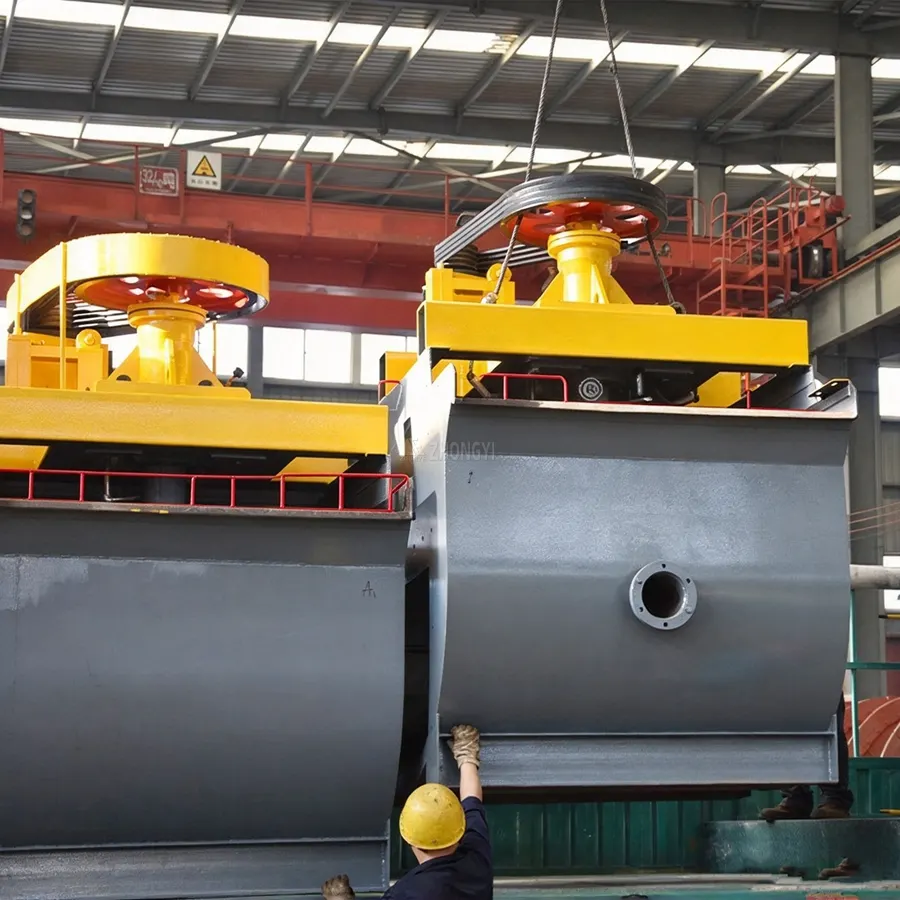
KYF flotation cells combine external air supply, mechanical agitation and a purpose-designed tank structure. These features support aeration and pulp circulation in continuous mineral flotation circuits.
KYF Flotation Cell Technical Specifications
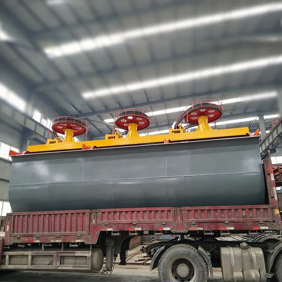
KYF flotation cells are available in several model sizes to suit different slurry flow rates and flotation duties. The table lists the main technical parameters, including effective volume, processing capacity, impeller speed, air pressure, motor power and equipment weight. Model selection depends on the required capacity and flotation circuit layout.
| Parametre | Specification Range |
| Model Series | KYF-1 to KYF-38 |
| Effective Volume | 1–38 m³ |
| İşleme Kapasitesi | 0.2–38 m³/min |
| Impeller Diameter | 340–880 mm |
| Impeller Speed | 139–281 r/min |
| Blower Air Pressure | Model-dependent, above 12.6–34.3 kPa |
| Maximum Aeration Rate | 2 m³/(m²·min) |
| Impeller Motor Power | 4–45 kW |
| Scraper Motor Power | 0.75–1.5 kW |
| Weight per Cell | 0.903–10.3 t |
KYF vs XCF Flotation Cell
KYF and XCF flotation cells differ mainly in slurry suction capability. KYF is designed for direct-flow operation without self-priming, while XCF can draw slurry into the cell. This difference affects equipment arrangement and pulp transfer within the flotation circuit.
| Feature | KYF Flotation Cell | XCF Flotation Cell |
| Slurry Suction | No self-priming capability | Self-priming capability |
| Air Supply | External blower | External blower |
| Impeller Design | Conical impeller with backward-inclined blades | Impeller assembly designed for slurry suction and agitation |
| Operating Duty | Direct-flow flotation | Suction and flotation |
| Circuit Layout | Requires suitable elevation or a separate slurry-transfer arrangement | Can draw slurry from an adjacent tank or feed point |
| Configuration Requirements | Pulp transfer must be considered in circuit design | Suction capability can simplify slurry transfer in suitable layouts |
| Typical Position | Direct-flow stages, including roughing or scavenging where appropriate | Feed or intermediate positions requiring suction |
How to Choose Between KYF and XCF?
Choose KYF when the circuit supports direct slurry flow and self-priming is unnecessary. Choose XCF when slurry needs to be drawn into the cell. In combined circuits, XCF can handle suction duties while KYF serves as a direct-flow cell.
KYF Flotation Cells Applications
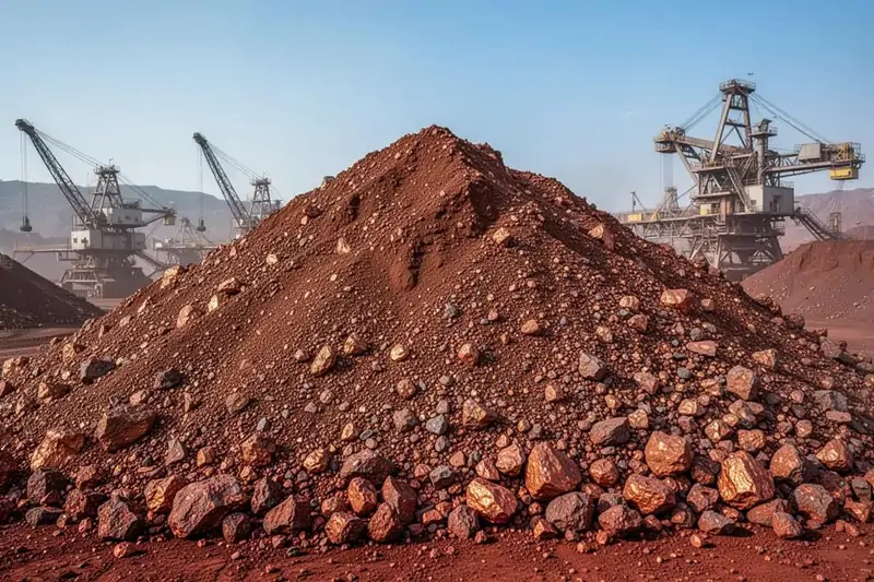
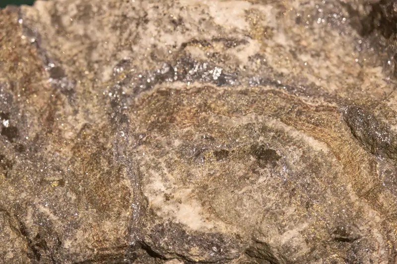
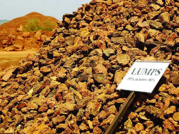
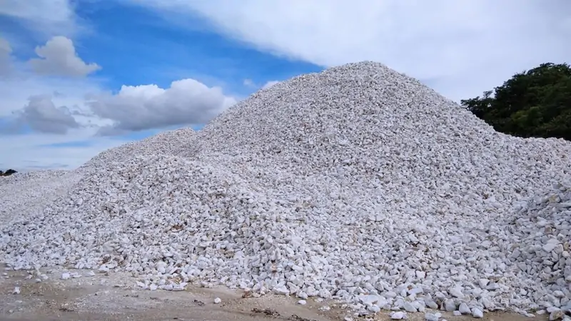
KYF flotation cells are used in mineral processing plants for the separation of valuable minerals from ore. Typical applications include sulfide ores, selected iron-bearing ores and non-metallic minerals, with cell configuration determined by ore properties and flotation circuit requirements.
How to Select a KYF Flotation Cell?
KYF flotation cells selection depends on slurry throughput, ore characteristics, aeration requirements and circuit layout. Evaluate the following six factors before determining the cell model and quantity.
Step 1: Determine the Required Pulp Throughput
Use the design slurry flow rate to estimate the required flotation capacity and number of cells. We also consider peak feed rates and expected production changes to avoid sizing the circuit around average throughput alone.
Step 2: Establish the Required Residence Time
The total working volume must provide sufficient residence time for the required flotation duty. Determine this from slurry flow rate and the residence time established through metallurgical testing or process design.
Step 3: Check Particle Size and Mineral Liberation
Grinding and classification determine whether valuable minerals are sufficiently liberated for flotation. Coarse particles can be harder to suspend and recover, while inadequate liberation may limit separation even when cell capacity is sufficient.
Step 4: Assess Pulp Density and Flow Conditions
Pulp concentration and viscosity affect circulation, particle suspension and air dispersion. These conditions should be checked against the ore characteristics and operating requirements before confirming the cell model.
Step 5: Size the External Air Supply
KYF cells rely on an external blower. Blower capacity must meet the combined airflow and pressure requirements of the operating cells, including losses through the air distribution system.
Step 6: Confirm the Flotation Circuit Layout
KYF cells do not self-prime slurry, so the circuit must provide suitable pulp transfer between stages. Depending on plant elevation and process requirements, this may involve a stepped arrangement or an XCF + KYF combination, with XCF providing slurry suction and KYF handling direct-flow flotation.
Do not select a KYF model by capacity alone. Cell volume, residence time, pulp conditions, air supply and slurry transfer must be considered together.
KYF Flotation Circuit Configuration
KYF flotation cells can be arranged individually or in multi-cell circuits, depending on plant capacity, flotation duty and slurry transfer requirements. Because KYF cells lack self-priming slurry capability, the circuit must provide a suitable method of pulp transfer between stages.
Single KYF Cell
A single KYF cell may be used for pilot testing or a specific duty within an existing flotation circuit. Its suitability depends on the required throughput, aeration conditions and slurry transfer arrangement. Feed and discharge conditions must be considered during process design.
Multiple KYF Cells in Series
Multiple KYF cells can be arranged in series for continuous rougher or scavenger flotation. Since KYF cells cannot self-prime slurry, a standalone circuit may require stepped installation to allow slurry to flow between cells. The necessary elevation difference depends on the plant layout and hydraulic requirements.
XCF + KYF Combined Flotation Unit
The XCF + KYF combination is suitable for flotation circuits that require both slurry suction and direct-flow operation. The XCF cell draws slurry into the tank, while KYF cells handle subsequent direct-flow duties. A common arrangement places an XCF cell at the head of a flotation stage, followed by KYF cells. Where process conditions permit, this configuration can support a level plant layout and reduce the need for stepped foundations or separate slurry-transfer pumps.
This arrangement is worth considering for medium- to large-scale plants where equipment elevation and slurry transfer affect plant layout. A standalone KYF circuit may still be suitable when stepped installation is practical. The final configuration should be based on ore characteristics, flotation test results, required residence time, hydraulic conditions and total project cost.
Why Choose Zhongyi Mining?
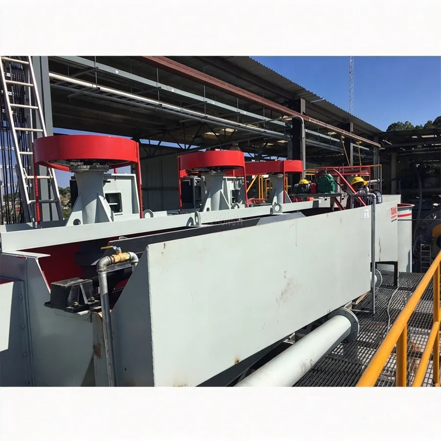
Founded in 2010, Zhongyi Mining integrates equipment design, R&D, manufacturing and installation. Our manufacturing base covers more than 40,000 m² and is equipped with over 60 sets of processing equipment. This in-house manufacturing capability supports equipment production and coordination across different stages of a mineral processing project.
Zhongyi Mining
Our engineering support extends from ore testing to equipment commissioning. Depending on project requirements, we provide ore identification, pilot testing, equipment selection and process flow design, working with specialist design institutes when additional technical input is required. This helps address process requirements before equipment specifications and installation arrangements are finalized.
Zhongyi Mining
We also supply equipment across multiple stages of mineral processing. Our product portfolio includes crushing, grinding, classification, flotation, magnetic separation and dewatering equipment. Zhongyi Mining has supplied equipment to large domestic mineral processing plants, magnesium plants and steel mills, giving us broader equipment-supply experience that can support projects requiring coordinated machinery rather than an isolated flotation unit.
Zhongyi Mining
Request a Customized Solution
Partner with Zhongyi for KYF flotation cells designed for rougher and scavenger flotation in mineral processing plants. Selection is based on ore characteristics, processing capacity, pulp conditions, flotation requirements, and circuit layout.
Custom High Density Agitation Tank Solutions
Every KYF flotation project has different ore characteristics, processing requirements and plant layout constraints. Zhongyi provides equipment configurations tailored to your flotation duties and project scope, from individual cells for existing circuits to complete beneficiation lines. Explore our Mineral Flotasyon Tesisi Çözümleri for customized flotation circuits, or our Altın Madeni İşleme Tesisi Çözümleri for gold ore processing flowsheets that may incorporate flotation. Contact us with your ore type, target capacity and project requirements to discuss a suitable equipment configuration.
Please Provide the Following Information:
FAQs
What Is a KYF Flotation Cell?
A KYF flotation cell is a forced-air mechanical flotation machine used to separate valuable minerals from ore slurry. An external blower supplies air, while the impeller circulates pulp and disperses bubbles. KYF cells are commonly used in rougher and scavenger flotation circuits. The appropriate model and number of cells depend on ore characteristics, throughput, flotation test results and the plant’s process design.
How Does KYF Flotation Cells Work?
An external blower supplies air through the hollow shaft and air distributor, while the rotating impeller circulates slurry and disperses air bubbles. Hydrophobic mineral particles attach to bubbles and rise into the froth layer for collection. Other particles remain in the pulp and leave with the tailings stream or continue to the next stage. Performance depends on mineral liberation, particle size, reagent conditions, pulp density and airflow.
What Types of Ore Can KYF Flotation Cells Process?
KYF cells can be used in suitable flotation circuits for copper, lead-zinc, gold-bearing sulfide and selected iron-bearing ores. They may also be suitable for non-metallic minerals such as graphite and fluorite when froth flotation meets the separation requirements. Suitability depends on mineralogy, liberation size and reagent response. For complex ores, laboratory flotation tests should guide circuit design and equipment selection.
What Is the Difference Between KYF and XCF Flotation Cells?
Both KYF and XCF flotation cells use external air supply and mechanical agitation, but their slurry-handling functions differ. KYF cells operate in direct-flow duty and cannot self-prime slurry, whereas XCF cells have self-suction slurry capability. This affects equipment arrangement and pulp transfer between stages. The choice depends on plant elevation, slurry transfer requirements and the overall flotation flowsheet.
Can KYF and XCF Flotation Cells Be Used in the Same Circuit?
Yes. A common arrangement places an XCF cell at the beginning of a flotation stage to draw in slurry, followed by KYF cells for direct-flow operation. Where process conditions permit, this combination can support a more level plant layout and reduce the need for separate slurry-transfer pumps. The final arrangement depends on the process flowsheet, slurry levels, site elevations and hydraulic requirements.
How Do I Select the Right KYF Flotation Cells Capacity?
Capacity selection should consider slurry flow rate, required residence time, pulp density, particle-size distribution and the duty of each flotation stage. Cell volume alone is not enough; the number of cells and operating conditions also affect the design. Metallurgical test results and the process flowsheet should be reviewed to establish the required working volume and cell arrangement before confirming the model.
What Factors Affect KYF Flotation Cells Price?
The price of a KYF flotation cell depends on cell volume, configuration, construction materials, drive system and order quantity. Project costs may also include blowers, auxiliary equipment, spare parts, installation and commissioning. When comparing quotations, check whether the price covers an individual cell or a wider equipment package. Confirming the supply scope helps ensure that different quotations are compared on the same basis.
What Maintenance Does a KYF Flotation Cell Require?
Routine maintenance should cover the impeller, stator, shaft, air distributor and drive components. Check for wear, looseness, abnormal vibration, air-distribution problems and material buildup that may affect pulp circulation. Inspection intervals depend on ore abrasiveness, operating hours and site conditions. Follow the manufacturer’s maintenance instructions, and verify component dimensions and material requirements before ordering replacement parts.