What Is a Hydrocyclone Cluster?
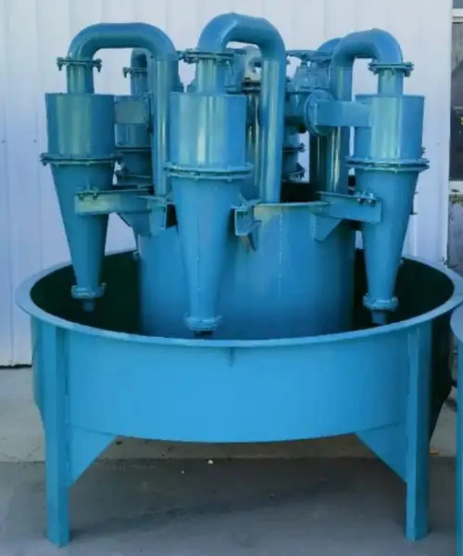
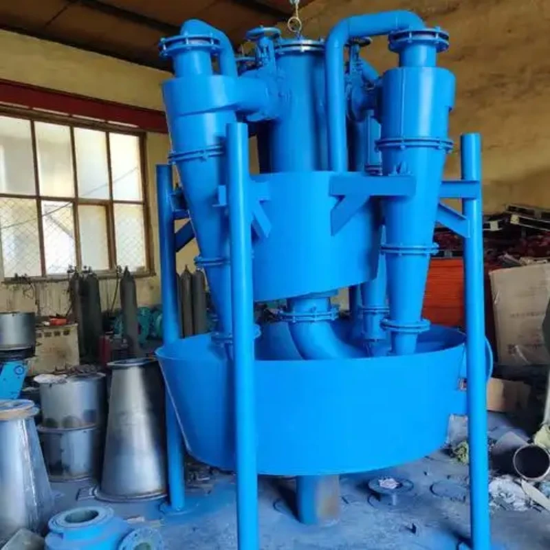
A Hydrocyclone Cluster, also known as a hydrocyclone battery, cyclone cluster, or hydrocyclone pack, is an integrated classification system consisting of two or more hydrocyclones arranged in parallel or staged configurations. The individual cyclones share feed distribution and overflow/underflow collection components, allowing the system to be configured according to slurry flow and separation requirements. In a typical mineral processing circuit, the cluster receives slurry from a grinding mill or slurry pump and separates coarse and fine particles before the overflow proceeds to flotation, concentration, thickening, or other downstream processes, while the underflow can return to the mill for further grinding.
The cluster uses the same centrifugal classification principle as an individual hydrocyclone. Pressurized slurry enters each cyclone tangentially, creating an outer vortex that carries coarser or denser particles toward the underflow and an inner vortex that carries finer particles toward the overflow. Parallel operation increases overall throughput, while staged arrangements can be used when additional classification is required. With two or more cyclones working as a unit, the system also allows the operating configuration to be adjusted to match changing process capacity and slurry conditions.
How Does a Cyclone ClusterWork?
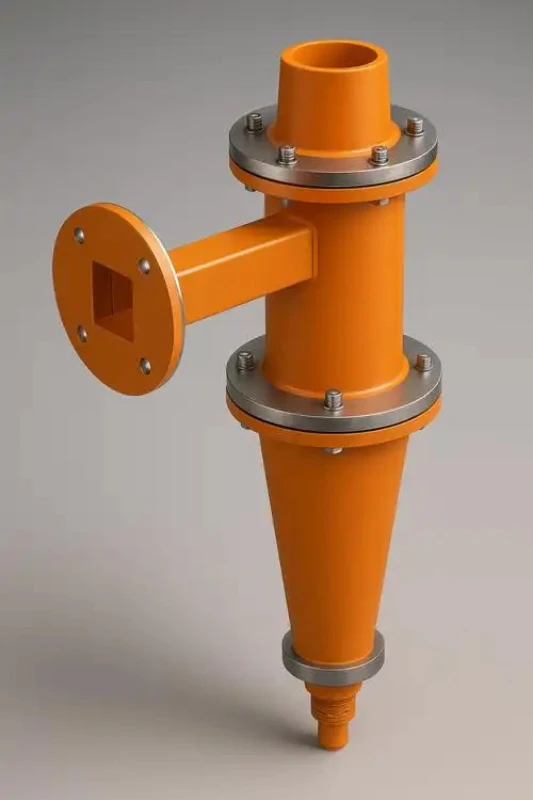
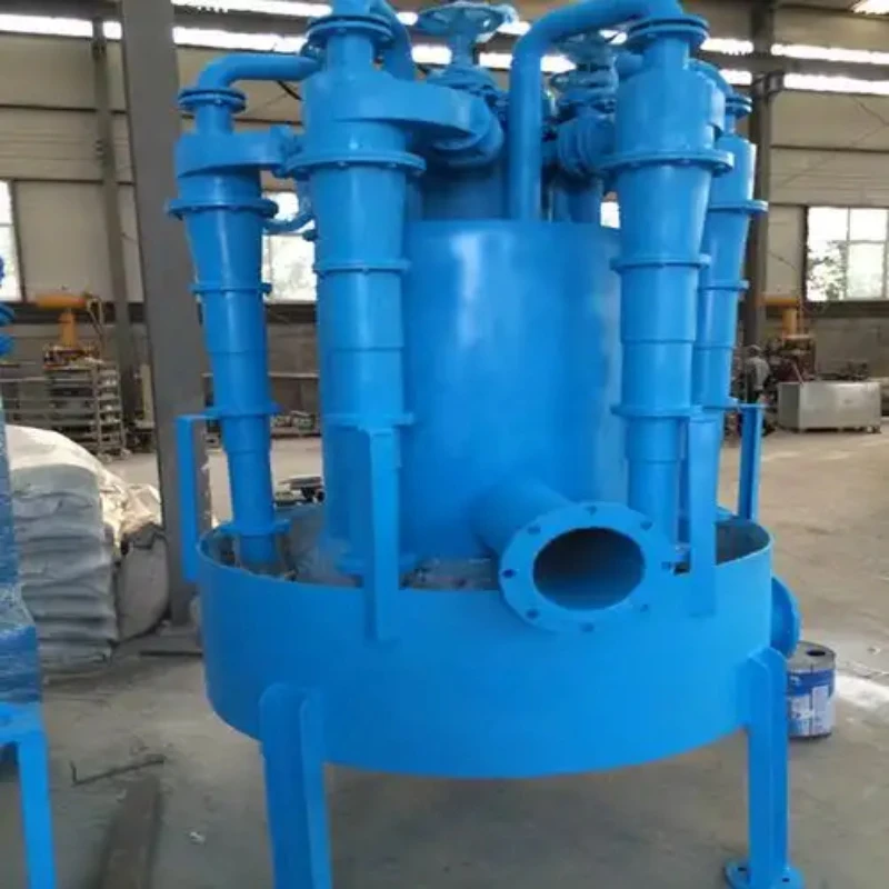
A Hydrocyclone Cluster operates by distributing pressurized slurry through a common feed manifold to multiple hydrocyclones working in parallel. The slurry enters each cyclone tangentially or through an involute inlet, creating a high-speed rotating flow. Balanced feed pressure and flow between individual cyclones are important for maintaining consistent classification performance.
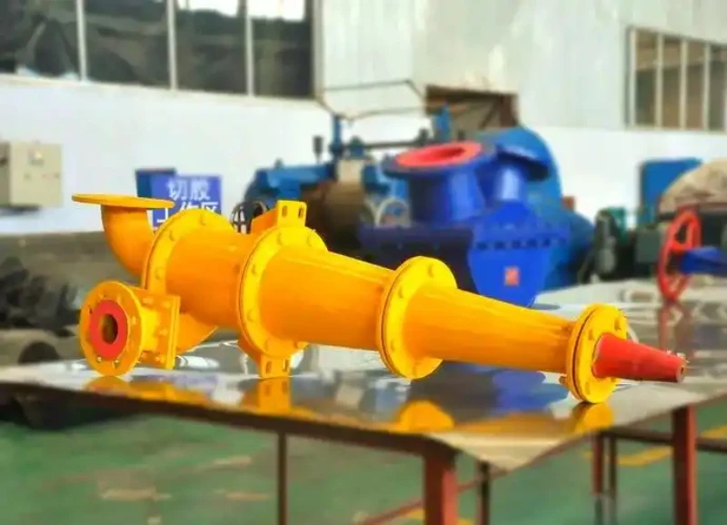
Inside each hydrocyclone, centrifugal force drives coarse and dense particles toward the cyclone wall and downward to the apex, while finer particles move toward the central axis and rise through the vortex finder as overflow. The separation is therefore controlled by the cyclone’s internal flow pattern, feed conditions, and component dimensions such as the vortex finder and apex.
The separated streams from each cyclone are collected through common overflow and underflow launders. Fine particles in the overflow can proceed to flotation, concentration, thickening, or other downstream processes, while the coarser underflow may return to a ball mill for further grinding or enter another separation stage. Running multiple cyclones simultaneously increases total slurry handling capacity while allowing the operating configuration to match actual process requirements.
Hydrocyclone Pack Components
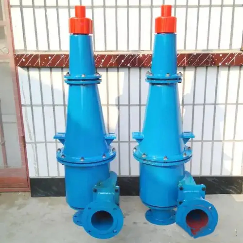
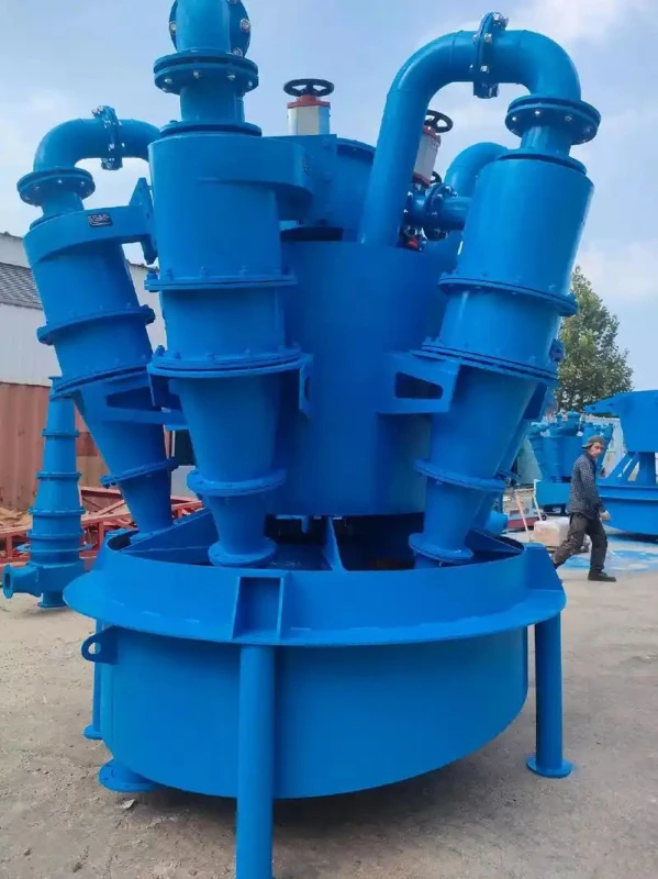
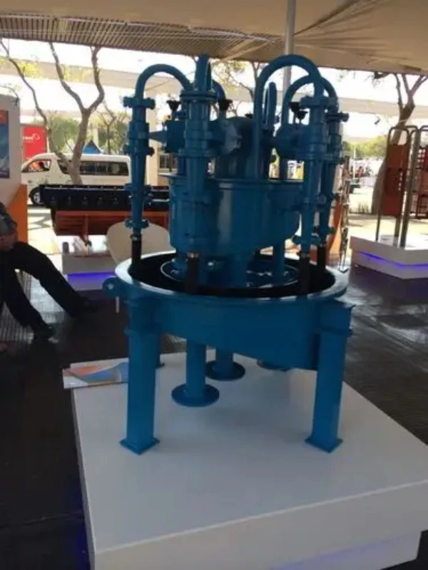
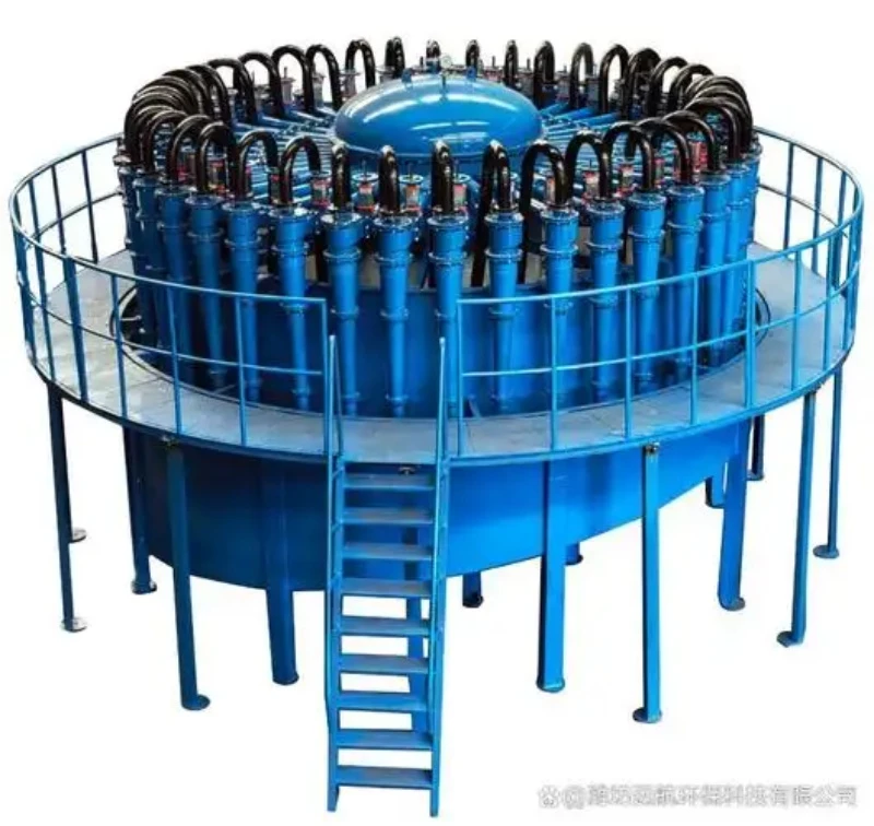
A hydrocyclone cluster consists of multiple hydrocyclones and shared slurry distribution, collection, and control components. Each part supports stable classification, material discharge, or routine maintenance.
Hydrocyclone Cluster Design and Sizing
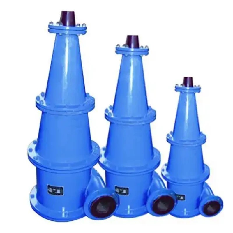
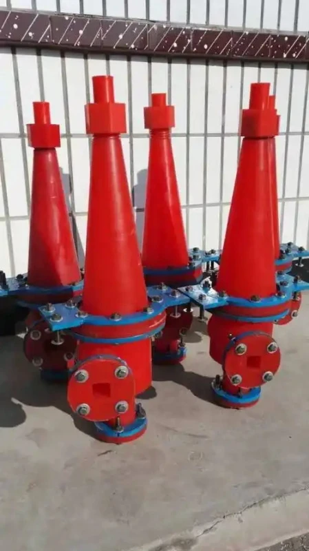
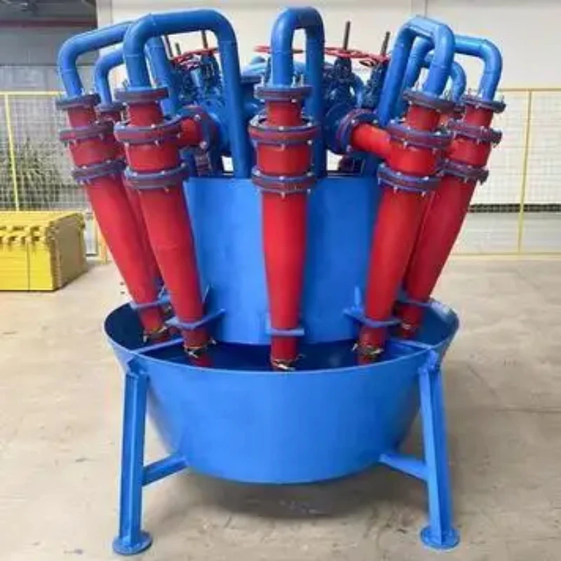
Sizing starts with the required slurry flow and target separation. Cyclone diameter, operating pressure, number of units, and standby capacity are then selected according to the process conditions.
Hydrocyclone Cluster Technical Specifications
The following specifications are based on the FX-series hydrocyclone data provided. For a cluster configuration, the final number of cyclones, operating/standby arrangement, manifold design, and total cluster capacity should be determined according to the required slurry flow and process conditions.
| Model | Diameter (mm) | Cone Angle (°) | Overflow Particle Size (μm) | Capacity (m³/h) | Overflow Pipe Diameter (mm) | Feed Inlet Area (mm²) | Apex Diameter (mm) | Overall Dimensions (L×W×H, mm) | Weight (kg) |
| FX-125 | 125 | 20 | 20–50 | 3.1–6.1 | 14, 18, 25, 35 | 25×10 | 15, 25 | 260×320×646 | 57 |
| FX-150 | 150 | 20 | 35–75 | 7.5–15 | 20, 40, 32, 25 | 22×22 | 32, 24, 16 | 570×426×1123 | 128 |
| FX-250 | 250 | 20 | 40–100 | 10–39 | 26, 34, 50, 69 | 50×20 | 20, 25, 35 | 852×516×1273 | 205 |
| FX-300 | 300 | 20 | 45–105 | 37–43 | 65, 75 | 47×60 | 35, 40 | 852×525×1940 | 287 |
| FX-350 | 350 | 20 | 50–110 | 74–90 | 115, 105, 95 | 80×65 | 80, 70, 60 | 955×680×2299 | 430 |
| FX-500 | 500 | 20 | 60–120 | 170–220 | 180, 160, 140 | 110×120 | 110, 90, 70 | 1090×811×2835 | 718 |
Cluster HydrocycloneApplications
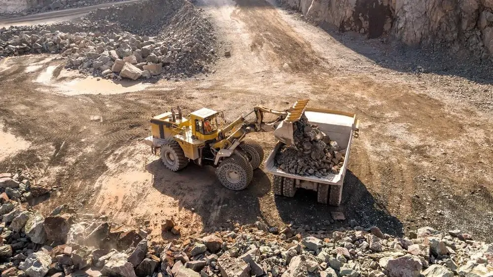
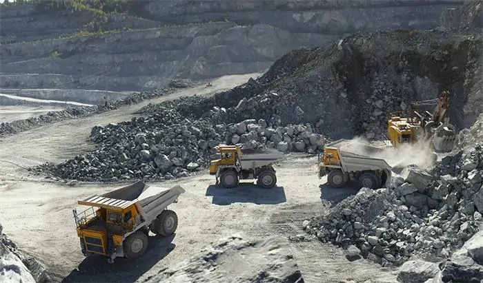
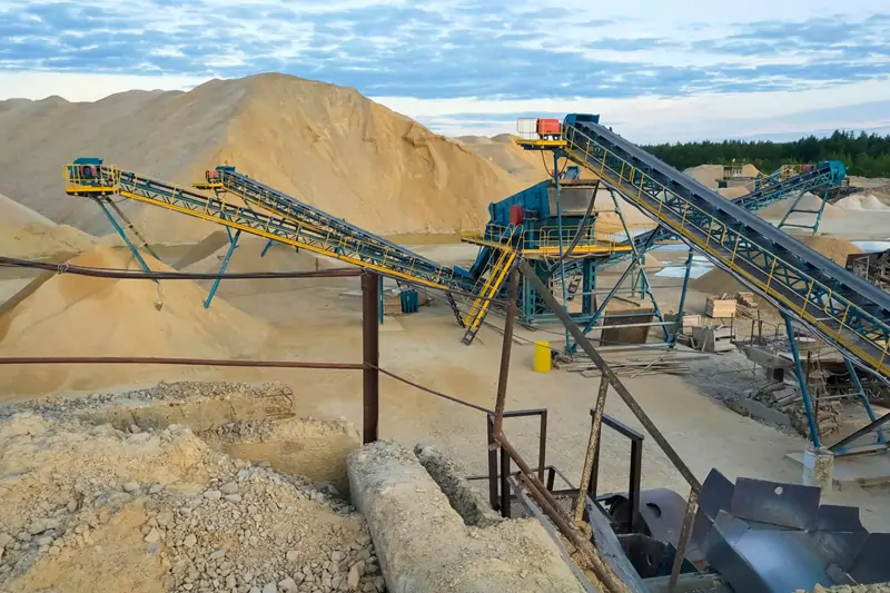
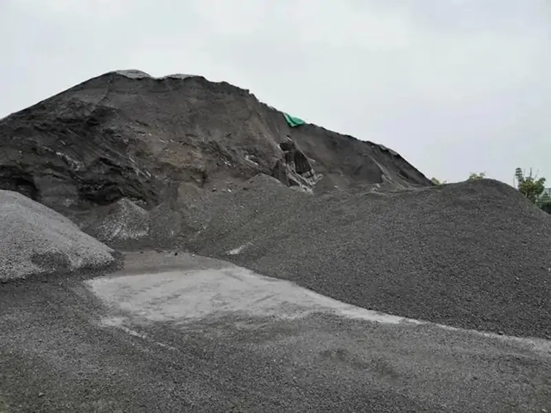
Hydrocyclone clusters are used in mineral processing plants where continuous slurry classification or separation is required at higher flow rates. Typical applications include:
What Affects Hydrocyclone Cluster Performance?
Hydrocyclone performance depends on slurry conditions and key cyclone dimensions. The main factors are:
- Feed Pressure: Determines slurry velocity, centrifugal force, capacity, and cut size. Excessive pressure can increase wear and power consumption without necessarily improving separation.
- Feed Solids Concentration: Affects slurry viscosity, particle interaction, pressure loss, underflow density, and classification sharpness. Higher concentrations can make particle separation less distinct.
- Particle Size Distribution: The proportion of coarse and fine particles affects cyclone loading and separation behavior. Changes in feed size distribution can shift the cut size and solids split between overflow and underflow.
- Vortex Finder and Apex Size: The vortex finder controls overflow discharge conditions and fine-particle reporting, while the apex controls underflow discharge. An undersized apex can cause roping, while an oversized apex can change underflow flow and solids distribution.
Hydrocyclone Pack vs Single Hydrocyclone
A single hydrocyclone and a Hydrocyclone Cluster use the same separation principle but differ in capacity, configuration, operating flexibility, maintenance, and application range. The comparison below highlights these key differences for mineral processing applications.
| Item | Single Hydrocyclone | Hydrocyclone Cluster |
| Throughput | Limited to one cyclone | Multiple cyclones operate in parallel |
| Feed Distribution | Direct feed to one unit | Common manifold distributes slurry to each cyclone |
| Capacity Adjustment | Limited by single cyclone capacity | Operating cyclone quantity can be configured according to flow requirements |
| Maintenance | May require shutdown or bypass | Individual cyclones can be isolated for maintenance |
| Footprint | Smaller for low-flow duties | Compact arrangement for higher-capacity applications |
| Control | Single cyclone operating conditions | System-level control of feed pressure and cyclone distribution |
| Typical Application | Small or lower-flow classification duties | Large mineral processing plants and high-volume slurry circuits |
Hydrocyclone Cluster Troubleshooting
Troubleshooting a Hydrocyclone Cluster requires checking both individual cyclones and the shared feed and discharge system. Common problems include uneven underflow, roping, coarse particles in the overflow, and excessive wear.
Uneven Underflow Between Cyclones
Uneven underflow may result from uneven feed distribution, different apex sizes, a blocked apex, pressure variation, or cyclone wear. Check the affected cyclone first, then inspect the common feed manifold and pressure distribution to determine whether the problem is limited to one unit or affects the cluster.
Roping at the Underflow
Roping occurs when the normal spray-shaped underflow changes into a rope-like discharge. Common causes include excessive solids loading, an undersized apex, insufficient dilution, and unstable operating pressure. Check slurry concentration, feed pressure, and apex condition before changing the operating configuration.
Coarse Particles in Overflow
Coarse particles in the overflow can be caused by excessive feed rate, low operating pressure, an unsuitable vortex finder, disturbed internal flow, or abnormal feed density. Check the feed conditions and cyclone components to identify whether the problem comes from an individual cyclone or the overall cluster operation.
Excessive Wear
Excessive wear is mainly associated with abrasive minerals, high slurry velocity, operating pressure, liner material, and cyclone geometry. Regularly inspect the feed inlet, cone, vortex finder, apex, and internal liners, and replace worn components before dimensional changes begin to affect classification performance.
.webp)
Hydrocyclone Cluster Wear Protection
Hydrocyclone clusters continuously handle abrasive mineral slurry, making wear protection particularly important around the feed inlet, cone section, apex, vortex finder, and slurry manifolds. These areas are exposed to different levels of particle impact and sliding abrasion, so wear protection should be considered as part of the overall cyclone and cluster configuration.
Lining material is selected according to slurry abrasiveness, particle size, flow velocity, and operating conditions. Rubber lining is suitable for general abrasive slurry, while polyurethane provides wear and corrosion resistance and is commonly used for smaller cyclones. Ceramic lining is suited to highly abrasive duties where greater resistance to mineral wear is required.
For a complete cluster, we can configure the cyclone size, liner material, replaceable wear parts, and cluster layout according to the mineral characteristics, slurry conditions, and maintenance requirements. Individual cyclones and wear components can be inspected or replaced separately where the configuration allows, helping reduce unnecessary maintenance impact on the operating cluster.
Hydrocyclone Battery Selection Guide
Selecting a cluster hydrocyclone depends on the process duty, slurry characteristics, target separation size, required capacity, and plant layout. The key selection factors vary by application and should be evaluated together when determining cyclone size, operating quantity, and overall cluster configuration.
| Application | Main Selection Factors |
| Grinding Classification | Mill capacity; circulating load; target overflow P80; slurry density; number of operating cyclones |
| Desliming | Feed particle-size distribution; target desliming size; solids concentration; acceptable overflow solids loss |
| Tailings & Dewatering | Required underflow density; feed concentration; downstream thickener or filter requirements; underflow handling |
| High-Capacity Circuits | Total slurry flow; number of operating cyclones; standby requirement; manifold arrangement; available installation space |
Why Choose Our Hydrocyclone Cluster?
Our experience in mineral processing allows us to configure hydrocyclone clusters around actual plant conditions. We consider slurry flow, feed concentration, particle size, target cut size, operating pressure, cyclone quantity, and standby requirements when selecting the cyclone size and cluster arrangement.
With in-house design, processing, assembly, and inspection capabilities, we can manufacture the cyclone bodies, feed manifolds, launders, valves, and wear components as part of the same equipment package. This helps address practical requirements such as balanced feed distribution, wear protection, limited installation space, and convenient maintenance.
Our equipment and mineral processing services have supported projects involving Pangang Group, Kunming Iron & Steel, CHALCO, Western Mining, Zijin Mining, and Luoyang Molybdenum. We also provide equipment selection, process design, manufacturing, installation, and commissioning support, helping customers move from individual equipment requirements to a workable cluster configuration.
Request a Customized Solution
Work with Zhongyi to configure a Hydrocyclone Cluster for continuous slurry classification, balanced feed distribution, and reliable separation in mineral processing circuits.
Custom High Density Agitation Tank Solutions
Every mineral processing plant has different slurry flow, feed particle size, target separation size, and layout requirements. Tell us your processing capacity, slurry conditions, required classification size, cyclone quantity, and installation space, and our engineering team can configure the Hydrocyclone Cluster accordingly. For complete mineral processing requirements, you can also explore our Mineral Flotation Plants Solution for a broader process and equipment configuration. Contact us to discuss your project requirements and receive a suitable equipment configuration.
Please Provide the Following Information:
FAQs
What is a Hydrocyclone Cluster used for?
A Hydrocyclone Cluster is used for continuous slurry classification when one cyclone cannot provide the required capacity. Multiple hydrocyclones operate in parallel and share feed distribution, overflow collection, and underflow collection systems. It is commonly used in grinding circuits, desliming, tailings treatment, and other mineral processing applications requiring stable particle-size separation and continuous slurry handling.
How do I determine the right hydrocyclone cluster size?
Sizing starts with the required slurry flow rate, feed solids concentration, particle-size distribution, target separation size, and operating pressure. Cyclone diameter affects individual capacity and classification range, while the number of operating units determines total throughput. Installation space, standby requirements, slurry abrasiveness, and downstream process conditions should also be considered before finalizing the cluster configuration.
What happens if the slurry flow changes during operation?
Changes in slurry flow can affect cyclone pressure, capacity, cut size, and the distribution of solids between overflow and underflow. A cluster provides more operating flexibility because individual cyclones can be added to or removed from service where the configuration permits. The operating range should be established during design to ensure stable classification under expected minimum and maximum flow conditions.
What feed pressure is required for a hydrocyclone cluster?
Required feed pressure depends on cyclone diameter, slurry properties, target separation size, and operating configuration. Pressure must be sufficient to generate the centrifugal flow required for classification, while excessive pressure can increase wear and energy consumption. During operation, pressure should remain reasonably stable across the feed manifold. Significant pressure differences between individual cyclone inlets should be investigated.
Can individual cyclones be isolated for maintenance?
Yes. A properly configured cluster can use individual isolation valves so that one cyclone can be removed from service while the remaining units continue operating. This is useful for inspection, cleaning, apex replacement, or liner maintenance. The number of operating and standby cyclones should be determined during design according to the required process capacity, maintenance requirements, and acceptable reduction in classification capacity during servicing.
Why does a hydrocyclone cluster produce uneven underflow?
Uneven underflow can indicate unbalanced feed distribution, pressure differences, blocked or worn apexes, or differences between cyclone components. Start by comparing the affected cyclone with the others and checking its apex and feed inlet. If several cyclones show abnormal discharge at the same time, inspect the common feed manifold, slurry conditions, and pressure distribution rather than changing individual components immediately.
How can excessive wear be reduced?
Wear is mainly influenced by slurry abrasiveness, particle size, flow velocity, operating pressure, cyclone geometry, and lining material. The feed inlet, cone section, apex, vortex finder, and manifolds generally require particular attention. Rubber, polyurethane, or ceramic lining can be selected according to operating conditions. Regular inspection and timely replacement of worn components help prevent dimensional changes from affecting classification performance.
What information is needed to configure a Hydrocyclone Cluster?
For a suitable configuration, customers should provide slurry flow or processing capacity, feed solids concentration, slurry density, particle-size distribution, target overflow P80 or cut size, and operating pressure. Plant layout information is also useful, including available installation space, inlet and outlet arrangement, and preferred operating or standby cyclone quantity. These parameters provide the basis for selecting cyclone size and cluster configuration.