GBJ Double Impeller Leaching Agitation Tank Overview
What Is a GBJ Double Impeller Leaching Agitation Tank?
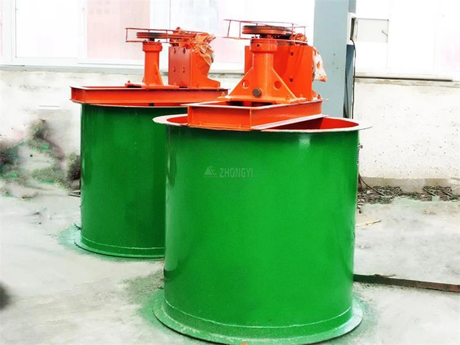
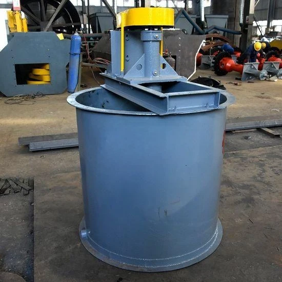
The GBJ Double Impeller Leaching Agitation Tank, also known as a double impeller leaching tank, double impeller agitation tank, or cyanide leaching tank, is a mineral processing vessel designed for continuous slurry agitation and leaching. It is primarily used in gold cyanidation, Carbon-in-Pulp (CIP), and Carbon-in-Leach (CIL) circuits, where stable slurry conditions are required for effective leaching and adsorption. The tank is normally installed downstream of grinding, classification, and thickening equipment and can be integrated with carbon screens, slurry pumps, and other equipment in the processing circuit.
What Is the GBJ Tank Used For?
The GBJ tank is mainly used for gold leaching and slurry conditioning, particularly where finely ground, low-viscosity slurry needs controlled agitation during the reaction stage. Typical reference conditions include -200 mesh material accounting for more than 90% of the feed and slurry concentration below 45%. Depending on the process design, the tank can also be used for reagent mixing and related hydrometallurgical applications. Tank volume, quantity, and operating configuration should be selected according to plant capacity, slurry characteristics, and required leaching residence time.
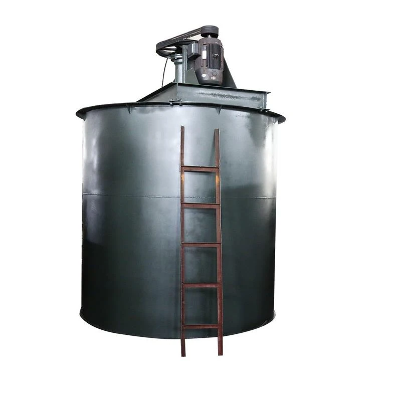
GBJ Double Impeller Leaching Agitation Tank Structure
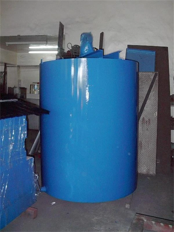
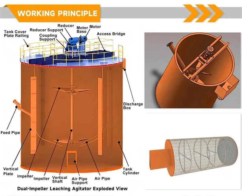
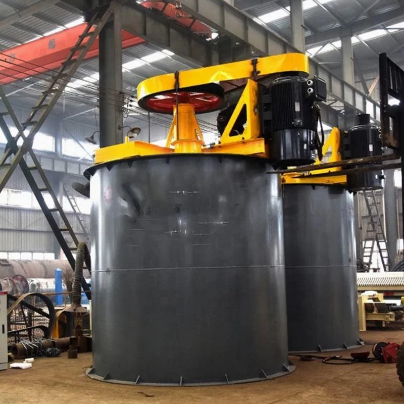
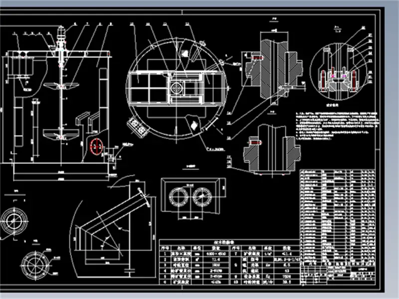
The unit consists of a cylindrical tank body, drive assembly, hollow shaft, upper and lower impellers, aeration system, and internal baffles. Each component works together to maintain stable slurry agitation and aeration during gold leaching, CIL, and CIP operations.
- Tank Body: The cylindrical tank provides the working volume for slurry mixing and leaching. Carbon steel is commonly used for the main structure, with rubber or other protective linings available for abrasive or corrosive slurry conditions.
- Drive Assembly: The drive system consists of the motor, reducer, coupling, bearing assembly, and vertical shaft. It provides stable power transmission for continuous impeller operation.
- Double Impellers: Upper and lower impellers are installed at different positions on the vertical shaft. Their large-diameter, low-speed configuration provides steady slurry suspension and controlled agitation.
- Hollow Shaft and Aeration System: The hollow shaft provides an internal passage for air delivery to the lower part of the tank. The aeration system supplies air to support the leaching process under the required operating conditions.
- Baffles and Auxiliary Components: Internal baffles help control slurry movement and reduce excessive vortexing. Auxiliary components include air valves, shaft seals, inspection openings, and slurry connections. CIL and CIP circuits may also include carbon screens and carbon transfer equipment.
How Does a GBJ Double Impeller Leaching Agitation Tank Work?
In a leaching circuit, simply keeping the slurry moving is not enough. The equipment must maintain a consistent suspension, provide sufficient contact between the ore slurry, reagents, and air, and keep the material moving through the tank without creating significant dead zones. This is particularly important in gold cyanidation, where stable agitation and aeration directly affect the conditions available for the leaching reaction. The GBJ Double Impeller Leaching Agitation Tank works by using two vertically arranged impellers to drive slurry circulation while air and leaching reagents are dispersed through the slurry.
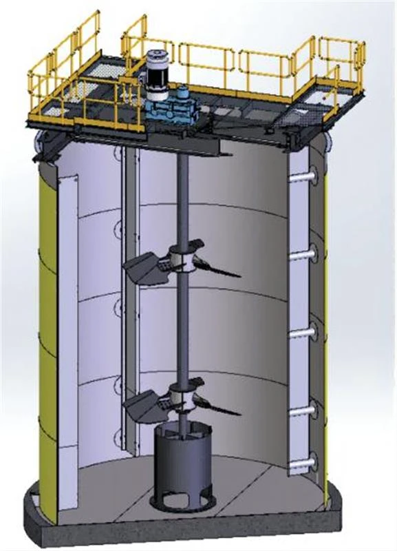
During operation, the incoming slurry is driven downward through the central area of the tank by the upper and lower impellers and then spreads outward near the bottom. Air enters through the hollow shaft and is dispersed into the agitated slurry, while internal baffles help guide circulation and limit excessive vortexing. The resulting flow keeps fine mineral particles suspended and promotes continuous contact between mineral surfaces, leaching reagents, and dissolved oxygen. After the required residence time, the uniformly mixed slurry flows to the next leaching or adsorption stage.
GBJ Double Impeller Leaching Agitation Tank Advantages
The GBJ Double Impeller Leaching Agitation Tank combines a two-level impeller arrangement, hollow-shaft aeration, and low-speed agitation to handle continuous slurry mixing in leaching circuits. These design features work together to improve slurry circulation, air dispersion, and operating stability while keeping wear and maintenance requirements under control.
GBJ Double Impeller Leaching Agitation Tank for Gold Extraction
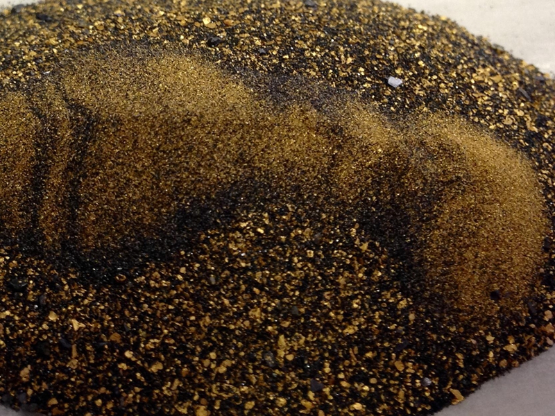
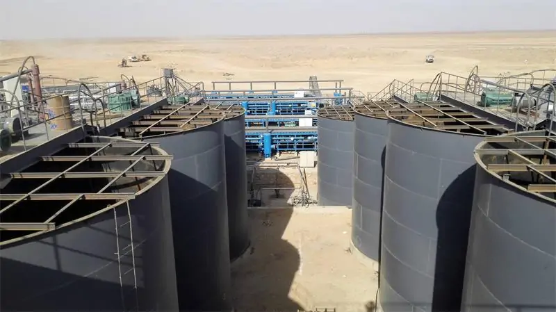
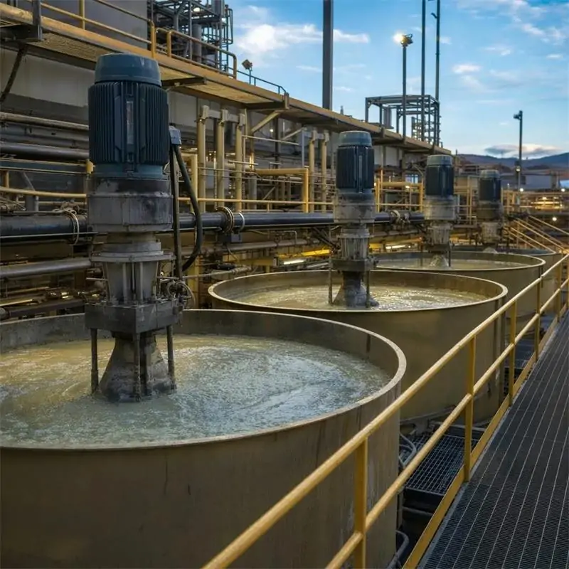
The GBJ Double Impeller Leaching Agitation Tank is used in gold cyanidation circuits at the leaching stage. It is normally installed after grinding and classification, where prepared ore slurry is mixed with the leaching solution before moving to the next stage. The tank creates the mixing conditions needed for gold dissolution rather than recovering gold itself.
Slurry Conditions and Application Range
Selecting a leaching agitation tank requires more than checking processing capacity. Particle size, slurry concentration, viscosity, settling behavior, and ore characteristics all affect the required tank configuration. The following conditions are typical reference values, while final selection should be based on the actual slurry and process requirements.
Particle Size and Slurry Concentration
A typical reference condition is -200 mesh material above 90%, with slurry concentration at ≤45%. These values are not fixed limits for every application. The actual grinding size and slurry concentration depend on ore properties, leaching requirements, slurry density, and the desired residence time.
Slurry Properties and Ore Characteristics
Slurry viscosity, solids density, settling behavior, and clay content directly affect agitation performance and power demand. Ore mineralogy and leaching kinetics should therefore be considered together with particle size and concentration when selecting the tank. For high-clay or difficult-to-suspend slurries, the impeller, motor, tank volume, and operating conditions may require additional engineering evaluation.
GBJ Double Impeller Leaching Agitation Tank Technical Specifications
The main specifications of the GBJ series are listed below. Standard models cover different working volumes, with impeller and drive configurations matched to the tank size.
| Model | Effective Volume (m³) | Impeller Speed (r/min) | Impeller Diameter (mm) | Motor Model | Motor Power (kW) | Weight (t) |
| GBJ-1000×1000 | 0.58 | 530 | 350 | Y112M-6 | 2.2 | 0.55 |
| GBJ-1250×1250 | 1.15 | 350 | 240 | Y100L2-4 | 3 | 1.11 |
| GBJ-1500×1500 | 2.2 | 320 | 420 | Y132M2-6 | 5.5 | 2.21 |
| GBJ-2000×2000 | 5.6 | 240 | 560 | Y160M-6 | 7.5 | 3.11 |
| GBJ-2500×2500 | 9.2 | 272 | 560 | Y180L-6 | 15 | 3.95 |
| GBJ-3000×3000 | 19.1 | 211 | 700 | Y225S-8 | 18.5 | 4.61 |
| GBJ-4000×4000 | 45 | 153 | 1000 | Y250M-8 | 37 | 9.56 |
How to Select a GBJ Leaching Agitation Tank?
Selecting a GBJ Double Impeller Leaching Agitation Tank requires matching the tank to the process conditions, not simply choosing a model based on capacity. The main factors include slurry flow rate, residence time, effective volume, impeller configuration, aeration, material selection, and drive system. The following three aspects provide a practical basis for equipment selection.
Determine Tank Volume and Quantity
The required effective volume can be estimated from slurry flow rate and required residence time:
Required Effective Volume = Slurry Flow Rate × Required Residence Time
For continuous leaching, the total volume is normally divided among multiple tanks arranged in series. Tank quantity depends on the required residence time, operating volume, process stages, and whether the circuit uses CIL or CIP. Plant capacity alone is therefore not enough to determine the number or size of tanks. Freeboard, operating level, tank geometry, and process margin should also be considered in the final design.
Match Impeller and Aeration Configuration
Impeller diameter, rotational speed, motor power, and aeration arrangement should be matched to the slurry conditions. Particle size, solids concentration, viscosity, settling behavior, and oxygen requirements all affect the agitation configuration. Typical reference conditions include material finer than 200 mesh accounting for more than 90% of the feed and slurry concentration below 45%. The final impeller and aeration arrangement should be determined from the actual process conditions rather than a fixed standard.
Select Materials and Drive Components
Tank lining, impeller material, shaft, reducer, motor, and sealing components should be selected according to abrasion, corrosion, and operating duty. Rubber-lined components are commonly used where wear protection is required, while drive and aeration configurations can be adjusted for specific process requirements. For CIL and CIP plants, the tank configuration should also be coordinated with carbon screens, carbon transfer equipment, slurry pumps, and the rest of the process flowsheet.
GBJ Double Impeller Leaching Agitation Tank Manufacturing and Quality Control
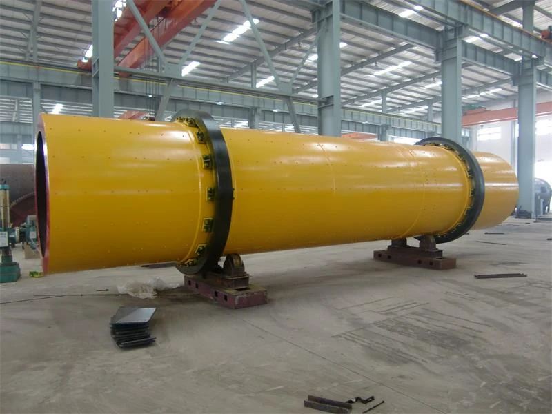
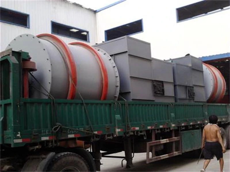
The manufacturing of a GBJ Double Impeller Leaching Agitation Tank involves several stages, from component fabrication and welding to mechanical assembly and final inspection. Each stage focuses on a different aspect of equipment reliability, with dimensional accuracy, alignment, wear protection, and operating performance checked before the tank is prepared for shipment.
Common Problems in GBJ Leaching Agitation Tank Operation
During continuous leaching operation, most problems are related to slurry suspension, aeration, agitation intensity, and mechanical loading. Identifying the operating cause rather than simply replacing a component helps reduce unplanned downtime and maintain stable leaching conditions.
Why Choose Zhongyi Machinery?
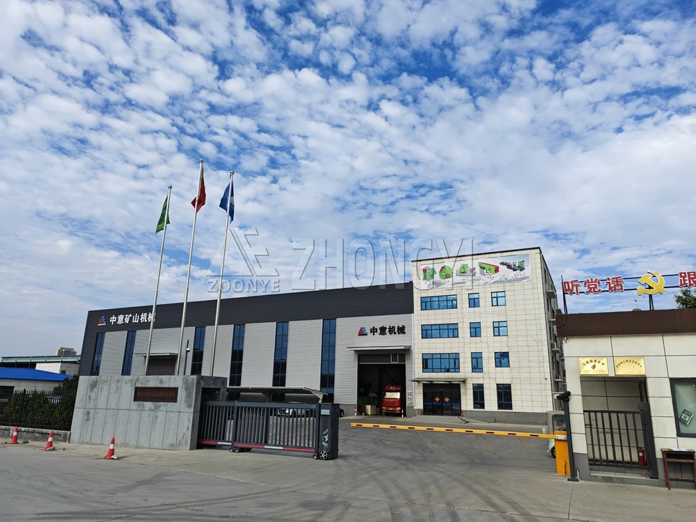
Zhongyi Machinery has more than 16 years of experience in mineral processing equipment manufacturing, with a 40,000+ m² production base and more than 60 sets of processing equipment. We manufacture and supply equipment for mining, metallurgy, chemical processing, and environmental applications, with products exported to Southeast Asia, West Asia, Africa, and Latin America.
Beyond equipment manufacturing, we support customers through ore testing, equipment selection, process design, installation, and commissioning. Our experience serving mining and metallurgical enterprises helps us address practical requirements such as slurry conditions, tank sizing, agitation configuration, and process integration, from equipment selection through site operation.
Request a Customized Solution
Partner with Zhongyi for a GBJ Double Impeller Leaching Agitation Tank engineered for stable slurry mixing, effective aeration, and reliable operation in gold leaching, CIL, CIP, and hydrometallurgical processing applications.
Custom Solutions
Every leaching circuit has different ore characteristics, slurry conditions, capacity, and residence-time requirements. Tell us your ore type, processing capacity, slurry concentration, particle size, and process requirements, and our engineering team can recommend the appropriate GBJ tank volume, quantity, agitation, aeration, and supporting equipment. Where a complete process is required, we can also integrate the tank into a [Mineral Flotation Plants Solution] and other mineral processing solutions. Contact Zhongyi Machinery for a tailored equipment recommendation and quotation.
Please Provide the Following Information:
FAQs
What Is a GBJ Double Impeller Leaching Agitation Tank?
A GBJ Double Impeller Leaching Agitation Tank is used for continuous slurry agitation and aerated leaching in mineral processing plants. Its two-level impeller arrangement promotes slurry circulation, while the hollow shaft can introduce air into the tank. It is commonly applied in gold cyanidation, CIL, CIP, and other hydrometallurgical processes requiring controlled mixing and aeration.
What Is a GBJ Leaching Agitation Tank Used For?
The tank is mainly used for gold cyanide leaching, CIL and CIP circuits, and other hydrometallurgical slurry processes. It keeps finely ground mineral pulp suspended and promotes contact between the ore, reagents, and air during the required residence time. The final application depends on slurry characteristics, process conditions, and the overall plant flowsheet.
Can GBJ Tanks Be Used for CIL and CIP Gold Processing?
Yes. GBJ tanks can be incorporated into both CIL and CIP gold processing circuits. In CIL plants, leaching and carbon adsorption occur in the same tank series, while CIP circuits normally use separate leaching and adsorption stages. Tank arrangement, volume, aeration, agitation, and carbon-handling equipment should be determined according to the specific process flowsheet.
What Particle Size and Slurry Concentration Are Suitable?
Typical reference conditions include material finer than 200 mesh accounting for more than 90% of the feed and slurry concentration below 45%. These values are not universal operating limits. Final selection should consider particle size distribution, solids density, viscosity, settling behavior, ore characteristics, and the residence time required by the leaching process.
How Do You Select the Required Leaching Tank Volume?
Required tank volume is primarily related to slurry flow rate and residence time. A basic calculation is Effective Volume = Slurry Flow Rate × Residence Time. For continuous leaching, the total volume is normally distributed among several tanks in series. Final sizing also considers operating level, freeboard, process stages, slurry characteristics, and available installation space.
Why Does Slurry Settle at the Bottom of a Leaching Tank?
Bottom settling usually occurs when agitation intensity is insufficient for the slurry’s solids concentration, particle size, or settling characteristics. Impeller diameter, rotational speed, and bottom clearance should be reviewed together. Excessive buildup should also be removed promptly, as accumulated solids can restrict circulation, reduce effective tank volume, and increase the mechanical load on the agitation system.
How Can Activated Carbon Wear Be Reduced in CIL or CIP Tanks?
Activated carbon wear is influenced by impeller speed, agitation intensity, slurry abrasiveness, and carbon movement within the circuit. Operating conditions should be balanced between adequate slurry suspension and excessive mechanical impact. Impeller condition, carbon screen arrangement, and carbon transfer equipment should also be checked when abnormal carbon loss or excessive fines are observed.
Can the GBJ Leaching Agitation Tank Be Customized?
Yes. GBJ tanks can be configured according to processing capacity, slurry characteristics, required residence time, and plant layout. Customization may include tank volume and dimensions, impeller configuration, motor and reducer selection, aeration arrangement, tank material, and protective lining. Customers should provide ore type, capacity, slurry conditions, process type, and site requirements for engineering evaluation.